3 - 38 XR Series RFID Readers Integrator Guide
General Purpose Input/Output
The XR Series of readers have a 15 pin port that can be used for manipulating reader operations and lights based
on input signals. These input signals can be triggered by motion sensors, photo eyes and other types of PLC
devices. The GPIO operates in two modes of operation:
•
With a Motorola Light Indicator Box (LIB) module
typical GPIO box
•
True GPIO
6 output pins and 6 inputs pins are available
GPIO Hardware
Refer to
GPIO Port Connections on page A-6
GPIO interface on the reader uses a SN74LVC4245A transceiver with Vcc=5V for first buffer. The maximum source
and sink currents is 250 mA. The input voltage thresholds are > 2V for High and < 0.8V for Low.
GPIO Usage
Reader supports BSP commands for setting state of output lines and reading state of input lines. Reader can also
be configured to notify host on specific GPIO input line changes. Refer to GPIO specific commands (40hex to
43hex) in the
XR Series RFID Readers, Software Interface Control Guide, p/n 72E-71803-xx
for details. If no
Motorola LIB is detected at power up, the device operates in the
True GPIO
mode. In this mode all 6 inputs and 6
output lines can be used using BSP GPIO commands.
Reader can be configured to perform tag reads in autonomous mode based on GPIO motion detection. Read
behavior is controlled by web interface settings, see
.
Web Interface Control
The reader can be configured to do continuous tag read whenever a motion senor line is kept triggered. This can
be done by doing the following steps:
1.
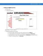
For all read point on which tag reading needs to be performed based on motion detection, set the Scan Period
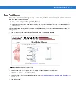
to Polled in corresponding read point class, see
Read Point Classes on page 3-25
.
2.
Check the
Enable Read on Motion Detection
check box in the
Reader Configuration
page, see
.
3.
Enabling
Reader Polling
from the
Scan Control
page, see
.
Reads can be triggered on
Left Motion Senso
r (mapped to Input 1) and
Right Motion Sensor
(mapped to Input 2) or
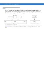
both. The reader is internally hard-coded to perform reads from specific read points based on the read point
configuration and on which motion sensor is triggered.
Area mode with LIB (Legacy Mode)
In the XR Series readers legacy mode of operation the tag read is performed on all read points when either the
LMS (
Left Motion Sensor
) or the RMS (
Right Motion Sensor
) is triggered. The left and right yellow LEDs are
interfaced to Motorola LIB light while reader is reading tags.
Содержание XR400
Страница 1: ...XR Series RFID Readers Integrator Guide ...
Страница 2: ......
Страница 3: ...XR Series RFID Readers Integrator Guide 72E 71773 08 Rev A December 2008 ...
Страница 6: ...iv XR Series RFID Readers Integrator Guide ...
Страница 14: ...xii XR Series RFID Readers Integrator Guide ...
Страница 74: ...3 46 XR Series RFID Readers Integrator Guide ...
Страница 86: ...4 12 XR Series RFID Readers Integrator Guide ...
Страница 95: ...Security 5 9 Figure 5 12 Connection Using PuTTY Client Window ...
Страница 106: ...5 20 XR Series RFID Readers Integrator Guide ...
Страница 110: ...A 4 XR Series RFID Readers Integrator Guide ...
Страница 124: ...Index 4 XR Series RFID Readers Integrator Guide ...
Страница 125: ......


