2 - 4
SE3300 Integration Guide
Housing Design
Design the engine’s housing so that internal reflections from the aiming and illumination system are not
directed back toward the engine. The reflections from the window or housing can cause problems, and for
particular window tilt angles, these reflections can bounce off the top or bottom of the housing and reach the
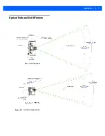
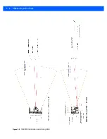
engine. Also, keep all housing elements outside the imaging field of view and usable illumination volume (see
and
). Avoid any bright objects around the engine that can be
reflected by a tilted window into the engine field of view and appear in a captured image.
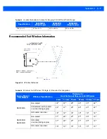
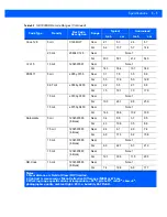
Recommended Exit Window Information on page 2-9
provides minimum exit window tilt angles. These
dimensional requirements can vary. Consider using baffles or matte-finished dark internal housing colors.
Optical
The SE3300 uses a sophisticated optical system that provides imaging performance that matches or exceeds
the performance of much larger imagers. However, an improperly designed enclosure, or improper selection of
window material, can affect the performance of the SE3300.
Positioning the Exit Window
Position the window so that illumination system light reflected off the inside of the window is not reflected back
into the engine (see
Recommended Exit Window Information on page 2-9
). If the designed enclosure cannot
accommodate the recommended window angle, contact Motorola to discuss positioning requirements. An
improperly positioned window can significantly decrease performance.
Tilted Window
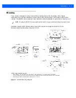
Use a tilted window for window positioning. Adhere to the minimum window tilt specifications in
. With tilted window installation, 2-sided anti-reflection coating is optional (see
).
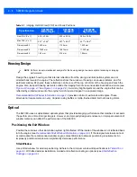
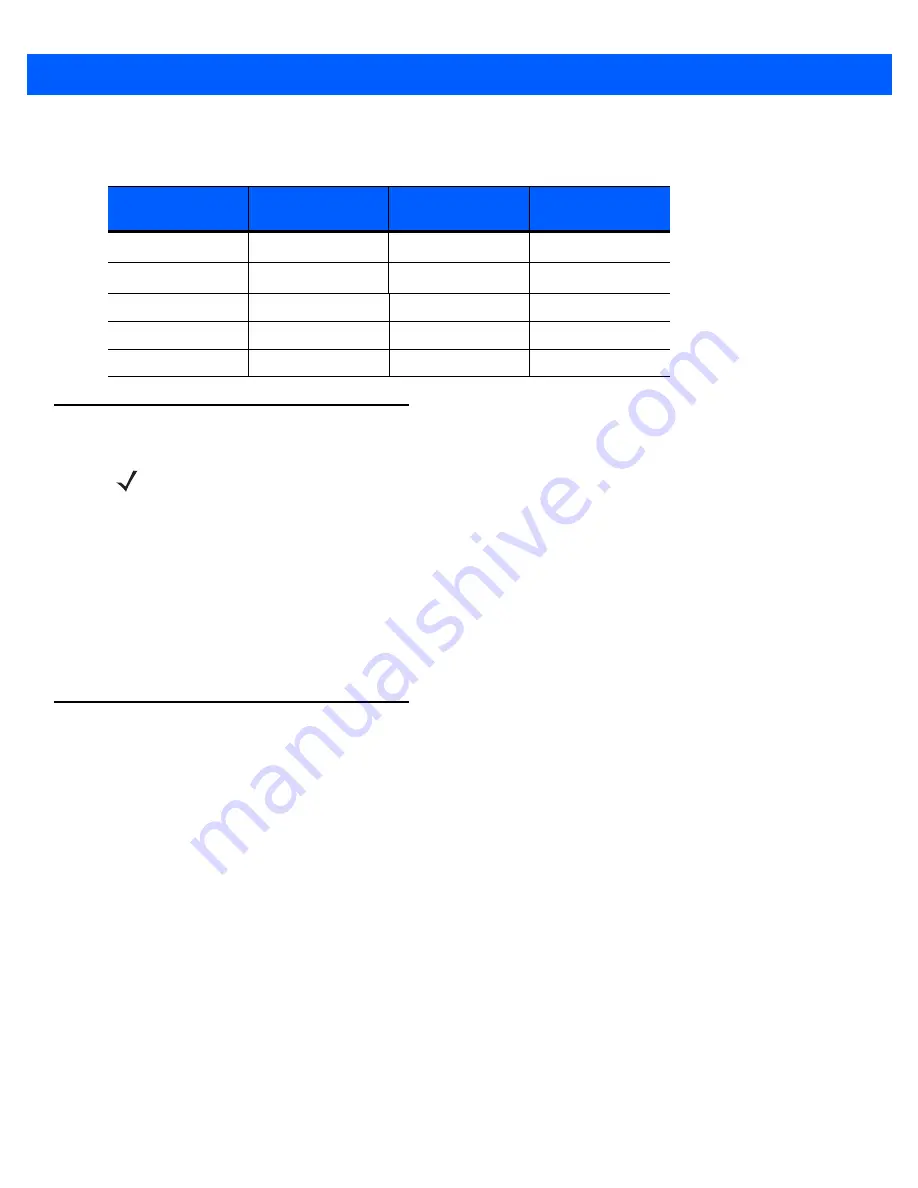
Table 2-1
Imaging Field of View (FOV) and Focus Positions
Specification
SE3300WA
(Wide Angle)
SE3300SR
Standard
SE3300HD
High Density
Nom FOV (X x Y)
46.1
o
x 30.4
o
39.2
o
x 25.4
o
38.4
o
x 24.9
o
Max FOV (X x Y)
50.1
o
x 34.4
o
42.7
o
x 28.9
o
42.7
o
x 28.9
o
Dimensions #3
1.429 mm
1.154 mm
1.429 mm
Dimensions #5
17.249 mm
16.974 mm
17.249 mm
Dimensions #6
1.63 mm
2.16 mm
1.89 mm
NOTE
Perform an opto-mechanical analysis for the housing design to ensure optimal scanning or imaging
performance.
Содержание SE3300
Страница 1: ...SE3300 INTEGRATION GUIDE ...
Страница 2: ......
Страница 3: ...SE3300 INTEGRATION GUIDE 72E 148589 01 Revision 8 September 2011 ...
Страница 6: ...iv SE3300 Integration Guide ...
Страница 10: ...viii SE3300 Integration Guide ...
Страница 14: ...xii SE3300 Integration Guide ...
Страница 18: ...1 4 SE3300 Integration Guide ...
Страница 26: ...2 8 SE3300 Integration Guide Figure 2 3 SE3300 Illumination and Aiming Path See Table 2 5 See Table 2 5 ...
Страница 38: ...3 10 SE3300 Integration Guide ...
Страница 41: ...Electrical Interface 4 3 Figure 4 2 21 Pin ZIF Connector SE3300 Imager to Flex Kyocera 6283 Series continued ...
Страница 42: ...4 4 SE3300 Integration Guide Figure 4 3 21 Pin ZIF Connector PL3307 Decoder to Flex Molex 54809 Series ...
Страница 43: ...Electrical Interface 4 5 Figure 4 4 21 Pin ZIF Connector PL3307 Decoder to Flex Molex 54809 Series continued ...
Страница 44: ...4 6 SE3300 Integration Guide Figure 4 5 SE3300 to PL33XX Decoder 21 Pin Flex ...
Страница 58: ...5 14 SE3300 Integration Guide ...
Страница 68: ...6 10 SE3300 Integration Guide ...
Страница 70: ...A 2 SE3300 Integration Guide ...
Страница 72: ......
Страница 73: ......


