background image

Wireless Applications 5 - 29

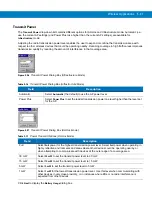
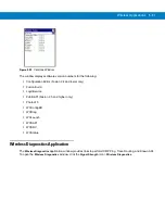
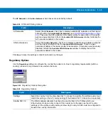
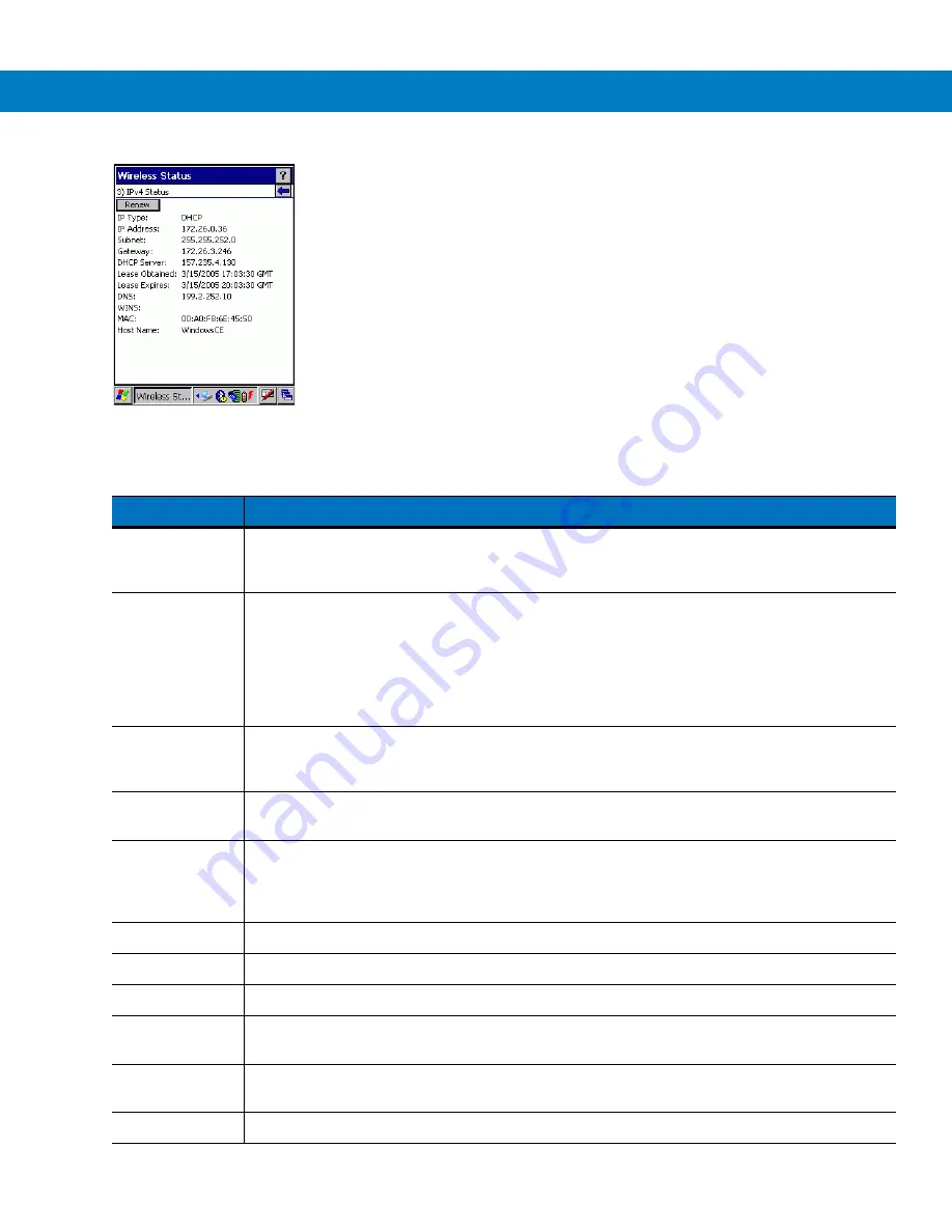
Figure 5-37    

IPv4 Status Window

Table 5-22    

IPv4 Status Fields

Field

Description

IP Type

Displays the IP type for the current profile: 

DHCP

 or 

Static

. If the IP type is DHCP, leased IP 

address and network address data appear for the reader. If the IP type is Static, the values 
displayed were input manually in the 

IP Config

 tab on 

page 4-19

.

IP Address

Displays the reader’s IP address. The Internet is a collection of networks with users that 
communicate with each other. Each communication carries the address of the source and 
destination networks and the particular machine within the network associated with the user 
or host computer at each end. This address is called the IP address. Each node on the IP 
network must be assigned a unique IP address that is made up of a network identifier and a 
host identifier. The IP address as a dotted-decimal notation with the decimal value of each 
octet separated by a period, for example, 192.168.7.27.

Subnet

Displays the subnet address. Most TCP/IP networks use subnets to manage routed IP 
addresses. Dividing an organization's network into subnets allows it to connect to the Internet 
with a single shared network address, for example, 255.255.255.0.

Gateway

Displays the gateway address. A gateway forwards IP packets to and from a remote 
destination.

DCHP Server

The Domain Name System (DNS) is a distributed Internet directory service. DNS translates 
domain names and IP addresses, and controls Internet e-mail delivery. Most Internet services 
require DNS to operate properly. If DNS is not configured, Web sites cannot be located or 
e-mail delivery fails. 

Lease Obtained

Displays the date that the IP address was obtained.

Lease Expires

Displays the date that the IP address expires and a new IP address is requested.

DNS

Displays the IP address of the DNS server.

WINS

WINS is a Microsoft Net BIOS name server. WINS eliminates the broadcasts needed to 
resolve computer names to IP addresses by providing a cache or database of translations. 

MAC

An IEEE 48-bit address is assigned to the reader at the factory to uniquely identify the adapter 
at the physical layer.

Host Name

Displays the name of the reader.

Содержание RD5000

Страница 1: ...RD5000 RFID Reader Integrator Guide ...

Страница 2: ......

Страница 3: ...RD5000 RFID Integrator Guide 72E 109786 01 Rev A March 2008 ...

Страница 4: ...om Motorola The user agrees to maintain Motorola s copyright notice on the licensed programs delivered hereunder and to include the same on any authorized copies it makes in whole or in part The user agrees not to decompile disassemble decode or reverse engineer any licensed program delivered to the user or any portion thereof Motorola reserves the right to make changes to any software or product ...

Страница 5: ...re listed below Change Date Description 01 Rev A 10 2006 Initial Release 02 Rev A 1 2008 Added External Antenna Software Update Version 1 1 Updated Chapter 5 Wireless Applications Added new Demo Application in Chapter 7 Replaced Chapter 8 Bluetooth Setup ...

Страница 6: ...iv RD5000 RFID Integrator Guide ...

Страница 7: ... 1 Unpacking the Reader 1 1 Connections and Ports 1 2 Accessories 1 4 Getting Started 1 4 Installing and Removing the Battery 1 5 Installing the Battery 1 5 Removing Replacing the Main Battery 1 6 Charging the Battery 1 7 Charging the Main Battery and Memory Backup Battery 1 7 Charging the Battery 1 7 Serial Communications 1 8 Charging Spare Batteries 1 9 Connect a USB Cable 1 10 Connect an Extern...

Страница 8: ...na Installation 2 12 Chapter 3 Accessories Introduction 3 1 Power Supply 3 2 Battery 3 2 Four Slot Spare Battery Charger 3 3 Setup 3 3 Spare Battery Charging with the Four Slot Spare Battery Charger 3 4 Battery Charging Indicators 3 4 Universal Battery Charger UBC Adapter 3 5 Inserting and Removing a Battery 3 5 Setup 3 6 Battery Charging Indicators 3 6 Charging Cable 3 7 Charging Cable With Seria...

Страница 9: ... 13 User Name 5 15 Password 5 15 Advanced Identity 5 16 Encryption 5 16 Key Entry Page 5 18 Passkey Dialog 5 18 IP Address Entry 5 19 Transmit Power 5 21 Battery Usage 5 22 Manage Profiles Application 5 22 Changing Profiles 5 23 Editing a Profile 5 24 Creating a New Profile 5 24 Deleting a Profile 5 24 Ordering Profiles 5 25 Export a Profile 5 25 Wireless Status Application 5 25 Signal Strength Wi...

Страница 10: ...eloper Kits 6 5 SMDK for C Contents and Locations 6 6 SMDK Patch for RD5000 6 6 Installing Other Development Software 6 6 Software Updates 6 6 Deployment 6 7 ActiveSync 6 7 Adding Programs 6 9 Adding a Program from the Internet 6 9 Creating Hex Images 6 10 Starting Terminal Configuration Manager 6 11 Defining Script Properties 6 13 Creating The Script For The Hex Image 6 14 Opening a New or Existi...

Страница 11: ...DDemo to Read Tags From a Remote Reader 7 3 Using RFIDDemo to Forward Log Tags to Remote Device 7 4 Launching the RFIDDemo Application 7 5 File Menu Options 7 6 About 7 6 Device Settings 7 7 Reader Device Settings 7 7 Tag Logging 7 7 Registry Settings Description 7 8 MPS Settings 7 12 Reader MPS Settings 7 12 Proximity Initiated Tag Read 7 13 Motion Initiated Tag Read 7 13 Tag Access Parameters 7 ...

Страница 12: ...and Off 8 3 Disable Bluetooth 8 3 Enable Bluetooth 8 3 Bluetooth Power States 8 4 Cold Boot 8 4 Warm Boot 8 4 Suspend 8 4 Bluetooth Profiles 8 5 Modes 8 6 Wizard Mode 8 6 Explorer Mode 8 9 Discovering Bluetooth Device s 8 10 Bonding with Discovered Device s 8 11 Renaming a Bonded Device 8 12 Deleting a Bonded Device 8 13 Accepting a Bond 8 14 Discovering Services 8 15 File Transfer Services 8 16 C...

Страница 13: ...ual COM Port Tab 8 28 Miscellaneous Tab 8 29 Tag Logging Setup Using RFID Demo Example 8 30 Chapter 9 Maintenance Troubleshooting Introduction 9 1 Maintaining the RFID reader 9 1 Battery Safety Guidelines 9 1 Troubleshooting 9 2 RFID Reader 9 2 Bluetooth Connection 9 4 Four Slot Spare Battery Charger 9 4 Appendix A Technical Specifications Technical Specifications A 1 RFID Reader A 1 Appendix B Mo...

Страница 14: ...xii RD5000 RFID Integrator Guide ...

Страница 15: ...describes how to use Microsoft developed applications Symbol Application Guide describes how to use Motorola developed applications RD5000 Quick Reference Guide QRG describes how to use the RD5000 RFID reader and provides the regulatory information RD5000 Integrator Guide describes how to set up the RD5000 RFID reader and the accessories SMDK Help File provides API information for writing applicat...

Страница 16: ...e covers the following configurations NOTE The RD5000 User Guide information is presented in the Quick Start Guide Configuration Radios Memory Data Capture Operating System Other RD5000 WLAN 802 11a b g WPAN Bluetooth 64 MB RAM 64 MB Flash RFID Windows CE 5 0 ...

Страница 17: ...cribes Bluetooth setup procedures and features Chapter 9 Maintenance Troubleshooting includes instructions on cleaning and storing the RFID reader and provides troubleshooting solutions for potential problems during RFID reader operation Chapter A Technical Specifications includes the technical specifications for the RFID reader Chapter B Motion Sensor Parameters describes the Motion Proximity sen...

Страница 18: ...e appropriate regional Support Center for contact information Before calling locate the model number and serial number Call the Support Center from a phone near the scanning equipment so that the service person can try to talk through the problem If the equipment is found to be working properly and the problem is symbol readability the Support Center will request samples of bar codes for analysis ...

Страница 19: ...onnectors A list of the accessories is provided in Table 1 2 Unpacking the Reader Carefully remove all protective material from around the reader and save the shipping container for later use Verify that all equipment was received RD5000 RFID reader Lithium ion battery Shock Isolators and mounting hardware QRG Quick Reference Guide Inspect the equipment for damage If any equipment is missing or if...

Страница 20: ...FID Reader Connections and Ports The RD5000 RFID reader has connections for Power input battery charging and serial communication USB communication External antenna Door Latch Proximity Sensor Battery Door Battery LED Power Button Error LED RFID Antenna ...

Страница 21: ... Connectors Description Power Serial Connection for external power battery charging and serial communications USB Client USB client connection External Antenna Supports one external antenna LAN Antenna USB Port Cover External Power Battery Charging and Serial Communications External Antenna Connector mini USB Port Termination Resistor Cover ...

Страница 22: ...Four Slot Spare Battery Charger Charges up to four spare batteries Universal Battery Charger Adapter Adapts the UBC for use with the reader batteries Charging Cable Connects to the power supply to provide battery charging power Charging Cable with Serial Communications Connects to the power supply and the battery charging and serial communications connector to provide battery charging power This c...

Страница 23: ... battery into the battery slot as shown in Figure 1 3 on page 1 5 Ensure the battery is fully inserted the battery release engages the battery when it is fully inserted 3 Close the battery door and rotate the door latch clockwise 1 4 turn to engage the battery door latch 4 If the battery was not fully charged before it was installed then the battery must be charged before the unit can be used To c...

Страница 24: ...t as shown in Figure 1 3 on page 1 5 Ensure the battery is fully inserted the battery release engages the battery when it is fully inserted If no battery is being inserted the unit can maintain the configuration settings for approximately 1 2 hour with a fully charged internal backup battery 5 Close the battery door and rotate the door latch clockwise 1 4 turn to engage the battery door latch Figu...

Страница 25: ...battery and backup battery retains data in memory for at least 72 hours Use the following to charge the main battery Accessories The reader charging cable provides charging capability Power supply and a charging cable The reader charging accessories are used to charge batteries that are removed from the reader Four Slot Spare Battery Charger Universal Battery Charger UBC Charging the Battery After...

Страница 26: ...Indicators LED Indication Description BATTERY LED Green Reader is on battery charge is greater than 80 Green Red Flash Reader is on green LED flashes red when charge is less than 80 Duration of the red flash increases as the battery charge drops At 79 very short red flash at 41 longer red flash Solid Red Battery charge is less than 40 at 20 a beeper sounds every second at 13 the unit turns off Off...

Страница 27: ...ry into the spare battery charging slot with the charging contacts facing down over the charging pins and gently press down on the battery to ensure proper contact 3 The battery starts to charge automatically The amber charge LED on the accessory lights to show the charge status See Chapter 3 Accessories for charging indications for the accessory The battery usually fully charges in less than four...

Страница 28: ...Cover 2 Connect the USB cable to the reader as shown in Figure 1 7 Figure 1 7 Connect the USB Cable CAUTION With the USB port cover removed the reader should only be operated in a clean dry environment for setup and configuration only The USB port cover must be replaced before operating the reader outside of a lab environment With the USB port cover removed the reader is not properly sealed Philli...

Страница 29: ...ed to the external antenna connector shown in Figure 1 10 on page 1 12 See External Antenna Installation on page 2 12 for external antenna installation procedures 3 Unscrew and remove the external antenna port termination resistor cover as shown in Figure 1 8 Figure 1 8 Remove the External Antenna Port Termination Resistor Cover CAUTION With the external antenna port termination resistor cover rem...

Страница 30: ... port as shown in Figure 1 9 Figure 1 9 Connect an External Antenna Cable to the Reader 5 Connect the external antenna to the external antenna port as shown in Figure 1 10 Figure 1 10 External Antenna Connection Reader External Antenna Connector External Antenna Connector External Antenna ...

Страница 31: ...on and setup procedures After the remote display application has been installed on the host computer set up an ActiveSync connection between the host computer and the RD5000 reader see Setting Up an ActiveSync Connection with no Partnership on the Host Computer on page 4 2 Start the remote display application to access the RD5000 RFID reader application Checking Battery Status The Battery LED disp...

Страница 32: ...cates the battery is fully charged and the reader is running on external power This icon indicates that the battery is fully charged 100 charged The battery status icons provide the battery status in 10 increments from 10 to 100 This icon indicates that the reader is connected to a host computer with a serial cable Wireless connection status icon Indicates WLAN signal strength The Bluetooth Enable...

Страница 33: ...lash memory is not lost In addition it returns formats preferences and other settings to the factory default settings Perform a warm boot first This restarts the reader and saves all stored records and entries If the reader still does not respond perform a cold boot Performing a Warm Boot Hold down the Power button see Figure 1 1 on page 1 2 for approximately five seconds As soon as the reader bat...

Страница 34: ...th for five seconds 3 Release the reset switch and the Power button The battery LED flashes yellow to indicate that a cold boot has initiated 4 Close the battery door and rotate the door latch see Figure 1 1 on page 1 2 counterclockwise 1 4 turn to lock The LED flashes several more times as the reader reboots and the battery LED lights green when the reader has completed the cold boot Figure 1 12 ...

Страница 35: ...installed Installing the RD5000 RFID reader consists of the following procedures Determine the mounting location Install the Motorola mounting brackets or prepare the mounting platform Install the shock isolators Mount the reader Mounting Location Select a mounting location that is free from obstructions that might inhibit reading and or interfere with the Proximity Sensor field of view and or WAN...

Страница 36: ...install the mounting brackets 1 Attach the shock isolators provided with the reader to the mounting brackets using the post side of the shock isolator and the provided nut Center the shock isolator post in the mounting hole and finger tighten the nut 2 Repeat the shock isolator mounting procedure for the second mounting bracket Figure 2 1 Mounting the Shock Isolators for the Welding Jig NOTE When ...

Страница 37: ...mounting brackets are identical so either bracket can be used on the left or right hand sides Figure 2 2 Welding Jig Installation 4 Position the mounting brackets welding jig assembly in the final mounting location and secure the assembly so that it will not move Lock Washers 4 Welding Jig Allen Head Screws 4 Mounting Bracket 2 ...

Страница 38: ...ing brackets in the six locations marked see Figure 2 3 The welds should be 1 2 inch to 3 4 inch long with a 1 4 inch bead and 1 16 inch penetration Figure 2 3 Tack Welds Location 6 Remove the welding jig and remove the shock isolators Tack Welds 6 places ...

Страница 39: ...bead and 1 16 inch penetration Figure 2 4 Finish Welding the Brackets 8 Clean and inspect the welds Re weld any areas that require touch up 9 Allow the brackets to cool before continuing with the installation 10 Clean and apply touch up paint as required to inhibit corrosion Finish Welds ...

Страница 40: ...ighten the nut Repeat the shock isolator mounting procedure for all four shock isolators Figure 2 5 Mounting the Shock Isolators 2 The mounting brackets are ready to accept the RD5000 RFID reader Proceed to Mounting The Reader on page 2 9 CAUTION The shock isolators are required Do not mount the unit without the shock isolators When permanently mounting the shock isolators use the lock washers bet...

Страница 41: ...taking into account the shocks and vibration the reader will experience Figure 2 6 on page 2 7 provides the placement and size specifications for the mounting platform Figure 2 6 Mounting Platform Specifications NOTE The locally fabricated mounting platform is only used when the Motorola mounting brackets are not or cannot be used CAUTION The supplied shock isolators are required and must be used ...

Страница 42: ... 1 Attach the shock isolators provided with the reader using the post side of the shock isolator as appropriate for the mounting platform design Center the shock isolator post in the mounting hole and secure Repeat the shock isolator mounting procedure for all four shock isolators 2 Proceed to Mounting The Reader on page 2 9 and adapt the procedure to fit the locally fabricated mounting platform r...

Страница 43: ...ot up return it to the local IT specialist to confirm operation 3 Once the proper boot up has been confirmed press the Power switch again to turn the reader off before proceeding with the installation The Battery LED should now be off Mounting on The Motorola Mounting Brackets The Motorola mounting brackets provide the proper clearances and provide protection from a flat object impacting the reade...

Страница 44: ...ting the RD5000 RFID Reader 3 Slide the reader over the shock isolators to align the shock mount holes with the reader mounting holes 4 If the holes do not align properly loosen the nuts at the bottom of the shock isolators and move the shock isolators to properly align the holes 5 When the holes are properly aligned insert the allen head screws and finger tighten External Antenna Terminating Resi...

Страница 45: ...eader Final Installation 6 Once all of the allen head screws are in place use a 3 16 inch allen wrench and a 7 16 open end wrench to tighten the allen screws and the shock isolator nuts to a torque of 3 3 ft lbs The reader is now ready for use ...

Страница 46: ...e as the RD5000 installation procedures Determine the mounting location Install the Motorola mounting brackets or prepare the mounting platform See Installing The Motorola Mounting Brackets on page 2 2 or Locally Fabricated Mounting Platform on page 2 7 for detailed procedures Install the shock isolators see See Installing The Shock Isolators on The Motorola Mounting Brackets on page 2 6 or Instal...

Страница 47: ...Battery Charger Charges up to four spare batteries Universal Battery Charger Adapter Adapts the UBC for use with the mobile reader batteries Charging Cable Connects to the power supply and the Battery Charging to provide battery charging power Charging Cable with Serial Communications Connects to the power supply and the Battery Charging and Serial Communications connector to provide battery charg...

Страница 48: ...ed before needing replacement Many factors affect the actual life cycle of a battery pack such as heat cold harsh environmental conditions and severe drops When batteries are stored over six 6 months some irreversible deterioration in overall battery quality may occur Store batteries discharged in a dry cool place removed from the equipment to prevent loss of capacity rusting of metallic parts and...

Страница 49: ...lot Spare Battery Charger Setup Figure 3 2 Four Slot Spare Battery Charger Power Connection Spare Battery Spare Battery Charging Well Spare Battery Charging LEDs 4 CAUTION Use only a Motorola approved power supply output rated 15 VDC and minimum 5 A Use of an alternative power supply will void the product warranty and may cause product damage Power Supply AC Cord DC Cable Power Port ...

Страница 50: ...amber LED is provided on each battery charging well see Figure 3 1 on page 3 3 See Table 3 1 for charging status indications The battery usually charges in less than four hours Table 3 1 Spare Battery LED Charging Indicators LED Indication Off Charger is not attached to the power supply correctly power supply is not powered or a battery is not inserted in the slot Fast Blinking Amber Charging erro...

Страница 51: ...onal information about the UBC2000 see the UBC 2000 Universal Battery Charger Product Guide p n 70 33188 xx Figure 3 3 UBC Adapter Inserting and Removing a Battery Insert the battery into the battery well with the charging contacts facing down over charging pins and gently press down on the battery to ensure proper contact To remove the battery press the battery release and lift battery out of the...

Страница 52: ...ically The charge LEDs see Figure 3 5 show the battery charging Table 3 2 shows battery charging status indications The battery usually charges in three hours Figure 3 5 UBC Adapter LEDs CAUTION Use only a Motorola approved power supply output rated 15 VDC and minimum 1 5 A Use of an alternative power supply will void the product warranty and may cause product damage Power Supply AC Line Cord DC C...

Страница 53: ...dapter READY or Green Charging complete STANDBY or Flashing Yellow The battery was deeply discharged and is being trickle charged to bring the voltage up to the operating level After operating level voltage is achieved the battery charges normally FAULT Yellow Charging error check placement of RFID reader spare battery CHARGING Yellow Normal charge Table 3 3 Power Serial Connector Pin Outs Pin Fun...

Страница 54: ...000 and a local computer The pin outs for the Power Serial Connector are provided in Table 3 3 on page 3 7 and the pin outs for the Serial RS232 Connector are provided in Table 3 4 Figure 3 7 Charging Cable With Serial Communications Table 3 4 Serial RS232 Connector Pin Outs Pin Function 2 RS232 Tx 3 RS232 RX 5 Gnd The Pin numbers are on the connector Serial RS232 Connector Power Serial Connector ...

Страница 55: ...g on the host computer To start select Start Programs Microsoft ActiveSync Figure 3 8 ActiveSync Not Connected 3 In the ActiveSync window select File Connection Settings The Connection Settings window displays Figure 3 9 Serial Connection Settings 4 For USB connection select Allow USB connection with this desktop computer 5 Click OK to save any changes made 6 Connect the device to the host compute...

Страница 56: ...10 Main Windows From main Explorer window see Figure 3 10 click Application CTLPANEL to access the CTLPANEL utility The CtlPanel window appears see Figure 3 11 Double click on Comm Settings to access the USB settings window Figure 3 11 Explorer Windows With Port highlighted confirm that the Com port default value is set to USB Default To change the value use the left and right arrow buttons to sel...

Страница 57: ...ounted antenna location The internal and the external antenna can operate independently from each other and can even have different power settings Both antennas can be active at the same time Figure 3 13 External Antenna See External Antenna Installation on page 2 12 for external antenna installation procedures See Connect an External Antenna on page 1 11 for external antenna connection procedures...

Страница 58: ...3 12 RD5000 RFID Integrator Guide ...

Страница 59: ...e step procedure that ensures the data is always safe and up to date Copies rather than synchronizes files between the reader and host computer Controls when synchronization occurs by selecting a synchronization mode e g set to synchronize continually while the reader is connected to the host computer or set to only synchronize on command Selects the types of information to synchronize and control...

Страница 60: ...allation is complete the ActiveSync Setup Wizard sets up communications between the RFID reader and host computer Before setting up communications between the RFID reader and host computer refer to the Chapter 3 Accessories for a list of the accessories that can be used 1 Connect the RFID reader to the host computer using the USB connection 2 If the Get Connected window does not appear on the host...

Страница 61: ... window see Figure 4 3 displays proceed to step 6 If the ActiveSync Connected window see Figure 4 7 displays proceed to step 11 Figure 4 2 Get Connected Window 6 In the ActiveSync Not Connected window select File Connection Settings The ActiveSync Connection Settings window appears Figure 4 3 ActiveSync Not Connected Window ...

Страница 62: ...check box Figure 4 4 ActiveSync Connection Settings Window 8 Click on OK The ActiveSync Add Remove Programs Window displays 9 Select any required programs to be added and click OK The ActiveSync Connecting Window displays Figure 4 5 ActiveSync Add Remove Programs Window ...

Страница 63: ...il ActiveSync connects Figure 4 6 ActiveSync Connecting Window 11 When Active Sync has connected the ActiveSync Connected window displays Figure 4 7 ActiveSync Connected Window 12 The ActiveSync Connected window indicated that ActiveSync has successfully connected ...

Страница 64: ...ter refer to the Chapter 3 Accessories for a list of the accessories that can be used To set up a partnership 1 Connect the RFID reader to the host computer using the USB connection 2 If the Get Connected window does not appear on the host computer select Start Programs Microsoft ActiveSync File Get Connected 3 Click Next to continue Figure 4 8 Get Connected Window 4 Select the Yes radio button to...

Страница 65: ...umber of Partnerships Window displays Figure 4 10 Add Remove Programs Window 7 Select the appropriate radio button for the number of computers to be included in the partnership Click Next the Select Synchronization Settings window displays Figure 4 11 Select Number of Partnerships Window ...

Страница 66: ...nnecting window displays may be very brief Figure 4 12 Select Synchronization Settings Window 9 The host computer and the RFID reader attempt to synchronize When the synchronization is complete the Setup Complete window see Figure 4 16 appears Figure 4 13 Connecting Window 10 If the ActiveSync Not Connected window see Figure 4 14 displays proceed to step 11 If the Setup Complete window see Figure ...

Страница 67: ...elect the Allow USB Connections check box and click Connect The ActiveSync Connecting window see Figure 4 13 displays may be very brief Figure 4 15 ActiveSync Connection Settings Window 12 When the synchronization is complete the Setup Complete window see Figure 4 16 appears Figure 4 16 Setup Complete Window ...

Страница 68: ...and all data is synchronized the RFID reader can be disconnect from the host computer For more information about using ActiveSync start ActiveSync on the host computer then see ActiveSync Help NOTE The first ActiveSync operation must be performed with a local direct connection To retain partnerships after a cold boot capture partnership registry information in a reg file and save it in the Flash F...

Страница 69: ... Setup Windows CE 5 0 The RD5000 USB setup is controlled through the CTLPanel The default setting is USB to confirm or change the setting perform the following From the RD5000 main window see Figure 4 18 click Start Programs Windows Explorer to access the Explorer application Figure 4 18 Main Windows From main Explorer window see Figure 4 18 click Application CTLPANEL to access the CTLPANEL utilit...

Страница 70: ...ttings to display the Comm Settings window Figure 4 20 Comm Settings Window 2 With Port highlighted use the left and right arrow buttons to select the value The default value is USB 3 Click OK to exit the Comm Settings window 4 Proceed with installing ActiveSync on the host computer and setting up a partnership ...

Страница 71: ...he reader a set of wireless applications provide the tools to configure and test the wireless radio in the reader The Wireless Application menu on the task tray provides the following wireless applications Wireless Status Wireless Diagnostics Find WLANs Manage Profiles Options Enable Disable Radio not available on Windows CE 5 0 devices with Fusion 2 3 and lower Log On Off Click the Signal Strengt...

Страница 72: ...ork is ready to use Good signal strength Wireless LAN network is ready to use Fair signal strength Wireless LAN network is ready to use Notify the network administrator that the signal strength is only Fair Poor signal strength Wireless LAN network is ready to use Performance may not be optimum Notify the network administrator that the signal strength is Poor Out of network range not associated No...

Страница 73: ...dows CE 5 0 with Fusion 2 4 and Higher To turn the WLAN radio off click the Signal Strength icon and select Disable Radio Figure 5 2 Disable and Enable Radio To turn the WLAN radio on click the Signal Strength icon and select Enable Radio Disable Radio Enable Radio ...

Страница 74: ...and encryption type The signal strength and encryption icons are described in Table 5 2 and Table 5 3 Network Type Type of network Channel Channel on which the AP is transmitting Signal Strength The signal strength of the signal from the AP NOTE The Find WLANs display is limited to 32 items ESSIDs or MAC addresses A combination of up to 32 ESSIDs APs may be displayed Manually enter valid ESSIDs no...

Страница 75: ...If creating a new profile the known information for that WLAN network appears in the fields Navigate through the wizard using the Next and Back buttons click X to quit On the confirmation dialog box click No to return to the wizard or click Yes to quit and return to the Manage Profiles window See Manage Profiles Application on page 5 22 for instructions on navigating the Profile Editor Wizard Prof...

Страница 76: ...endly name for the reader profile used to connect to either an AP or another networked computer Example The Public LAN ESSID The name and WLAN identifier of the network connection Alternatively enter the name and WLAN identifier of a WLAN network connection not listed on the Find WLANs window The ESSID is the 802 11 extended service set identifier The ESSID is 32 character maximum string identifyi...

Страница 77: ...ion is selected the Options Regulatory Country setting is not used For a single profile that can be used in multiple countries with infrastructure that supports 802 11d including Motorola infrastructure set the Profile Country to Allow Any Country Under Options Regulatory select Enable 802 11d The Options Regulatory Country setting is not used For a single profile that can be used in multiple coun...

Страница 78: ...t a channel number from the Channel drop down list Figure 5 6 Ad Hoc Settings Dialog Box 2 Click Next The Encryption dialog box displays See Encryption on page 5 16 for encryption options Table 5 6 Ad Hoc Channels Band Channel Frequency 2 4 GHz 1 2412 MHz 2 2417 MHz 3 2422 MHz 4 2427 MHz 5 2432 MHz 6 2437 MHz 7 2442 MHz 8 2447 MHz 9 2452 MHz 10 2457 MHz 11 2462 MHz 5 GHz 36 5180 MHz 40 5200 MHz 44...

Страница 79: ...ation Figure 5 8 Tunneled Authentication Dialog Box To select a tunneled authentication type Table 5 7 Authentication Options Authentication Description None Default setting when authentication is not required on the network EAP TLS Select this option to enable EAP TLS authentication EAP TLS is an authentication scheme through IEEE 802 1x It authenticates users and ensures only valid users can con...

Страница 80: ...y Microsoft as a PPP authentication protocol to provide better protection for dial up and virtual private network VPN connections With Windows XP SP1 Windows XP SP2 Windows Server 2003 and Windows 2000 SP4 MS CHAP v2 is also an EAP type TLS EAP TLS is used during phase 2 of the authentication process This method uses a user certificate to authenticate Table 5 9 TTLS Tunneled Authentication Options...

Страница 81: ...allenges the access client and the access client challenges the authenticating server If either challenge is not correctly answered the connection is rejected MS CHAP v2 was originally designed by Microsoft as a PPP authentication protocol to provide better protection for dial up and virtual private network VPN connections With Windows XP SP1 Windows XP SP2 Windows Server 2003 and Windows 2000 SP4...

Страница 82: ... is selected a server certificate is required Select a certificate on the Installed Server Certificates dialog box An hour glass may appear as the wizard populates the existing certificate list If the required certificate is not listed install it 1 Click the Install Certificate button Figure 5 11 Installed Server Certificates Dialog Box A dialog box appears that lists the currently loaded certific...

Страница 83: ... is not correct click the No button The wizard returns to the Installed Server Certs dialog box Figure 5 13 Confirmation Dialog Box Credential Cache Options If any of the password based authentication types were selected select the different credential caching options These options specify when the network credential prompts appear at connection on each resume or at a specified time Entering the c...

Страница 84: ...ns Description At Connect Select this option to prompt for credentials whenever the WCS tries to connect to a new profile Deselect this to use the cached credentials to authenticate If the credentials are not cached a prompt appears to enter credentials This option only applies when logged in On Resume Selecting this reauthenticates an authenticated user when a suspend resume occurs Once reauthent...

Страница 85: ...Name dialog box displays User Name The user name and password can be entered but is not required when the profile is created When a profile authenticates with credentials that were entered in the profile caching rules do not apply Caching rules only apply on credentials that are entered through the login dialog box Figure 5 17 Username Dialog Box Password Use the Password dialog box to enter a pas...

Страница 86: ...ity anonymous rather than a true identity plus any desired realm e g anonymous myrealm A user ID is required before proceeding Figure 5 19 Advanced Identity Dialog Box Click Next The Encryption dialog box displays Encryption Use the Encryption dialog box to select an encryption type The drop down list includes encryption types available for the selected authentication type See Table 5 12 for these...

Страница 87: ...anually entered in the edit boxes Only the required number of edit boxes for a key length is displayed 26 Hex digit value for 128 bit keys Use the Key Index drop down list to configure the four WEP keys The adapter uses the selected key Note The default Hex digit keys are visible any time they are used As a security precaution after setting the key values for the network the digits are replaced wi...

Страница 88: ... an encryption choose to enter a passkey by checking the Use PassKey check box The user is prompted to enter the passkey For WEP the Use PassKey checkbox is only available if the authentication is None When None is selected as an authentication and TKIP as an encryption passkey entry is required The user cannot enter a passkey if the encryption is TKIP and the authentication is anything other than...

Страница 89: ...dress fields are read only Static Select Static to manually assign the IP subnet mask default gateway DNS and WINS addresses the reader profile uses Table 5 14 Static IP Address Entry Fields Field Description IP Address The Internet is a collection of networks with users that communicate with each other Each communication carries the address of the source and destination networks and the particula...

Страница 90: ... is ignored and the IP information entered in the Microsoft interface applies Click Next The Transmit Power dialog box displays Table 5 15 IP Config Advanced Address Entry Fields Field Description G W The default gateway forwards IP packets to and from a remote destination DNS The Domain Name System DNS is a distributed Internet directory service DNS translates domain names and IP addresses and co...

Страница 91: ...wer Dialog Box Infrastructure Mode Field Description Automatic Select Automatic the default to use the AP power level Power Plus Select Power Plus to set the reader transmission power one level higher than the level set for the AP Table 5 17 Power Transmit Options Ad Hoc Mode Field Description Full Select Full power for the highest transmission power level Select Full power when operating in highl...

Страница 92: ...ge Profiles Figure 5 29 Manage Profiles Window Icons next to each profile identify the profile s current state NOTE Power consumption is also related to the transmit power settings Table 5 18 Battery Usage Options Field Description CAM Continuous Aware Mode CAM provides the best network performance but yields the shortest battery life Fast Power Save Fast Power Save the default performs in the mid...

Страница 93: ...fferent profiles to have pre defined operating parameters available for use in various network environments When the WLAN Profiles window displays existing profiles appear in the list Table 5 19 Profile Icons Icon Description No Icon Profile is not selected but enabled Profile is disabled Profile is cancelled A cancelled profile is disabled until a connect or login function is performed through th...

Страница 94: ...perating mode for the profile can be set Use the Profile Wizard to edit the profile power consumption and security parameters See Profile Editor Wizard on page 5 5 Creating a New Profile To create new profiles from the Manage Profiles window click and hold anywhere in this window Figure 5 32 Manage Profiles Add Select Add to display the Profile Wizard wherein the profile name and ESSID can be set ...

Страница 95: ...st and select Export from the pop up menu The Save As dialog box displays with the Application folder and a default name of WCS_PROFILE profile GUID reg Globally Unique Identifier Figure 5 33 Save As Dialog Box If required change the name in the Name field and click Save A confirmation dialog box appears after the export completes Wireless Status Application To open the Wireless Status window clic...

Страница 96: ...mware and hardware version numbers Quit exits the Wireless Status window Option windows contain a back button to return to the main Wireless Status window Signal Strength Window The Signal Strength window provides information about the connection status of the current wireless profile including signal quality missed beacons and transmit retry statistics The BSSID address shown as AP MAC Address di...

Страница 97: ...mmunicating with the radio card Status Indicates if the reader is associated with the AP Signal Quality Displays a text format of the Signal icon Tx Retries Displays a percentage of the number of data packets the reader retransmits The fewer transmit retries the more efficient the wireless network is Missed Beacons Displays a percentage of the amount of beacons the reader missed The fewer transmit...

Страница 98: ...en the IPv4 Status window click IPv4 Status in the Wireless Status window Table 5 21 Current Profile Window Field Description Profile Name Displays the current profile name the reader uses to communicate with the AP ESSID Displays the current profile ESSID name Mode Displays the current profile mode either Infrastructure or Ad Hoc Authentication Displays the current profile s authentication type E...

Страница 99: ...ys the subnet address Most TCP IP networks use subnets to manage routed IP addresses Dividing an organization s network into subnets allows it to connect to the Internet with a single shared network address for example 255 255 255 0 Gateway Displays the gateway address A gateway forwards IP packets to and from a remote destination DCHP Server The Domain Name System DNS is a distributed Internet di...

Страница 100: ... box displays 2 Navigate to the desired folder 3 In the Name filed enter a file name and then click OK A text file is saved in the selected folder Clearing the Log To clear the log click Clear Versions Window The Versions window displays software firmware and hardware version numbers This window only updates when it is displayed There is no need to update constantly The content of the window is de...

Страница 101: ...r only Fusion Build LoginService PublicAPI Fusion 2 5 and higher only Photon10 WCConfigED WCDiag WCLaunch WCSAPI WCSRV WCStatus Wireless Diagnostics Application The Wireless Diagnostics application window provides links to perform ICMP Ping Trace Routing and Known APs To open the Wireless Diagnostics window click the Signal Strength icon Wireless Diagnostics ...

Страница 102: ...ss Diagnostics window ICMP Ping Window The ICMP Ping window allows testing a connection at the network layer part of the IP protocol between the reader and an AP Ping tests only stop when the Stop Test button is clicked close the Wireless Diagnostics application or if the reader switches between infrastructure and ad hoc modes To open the ICMP Ping window click ICMP Ping in the Wireless Diagnostic...

Страница 103: ...ress or a DNS Name in the IP combo box and click Start Test The IP combo box should match the information shown in the ICMP Ping window s IP combo box When starting a test the trace route attempts to find all routers between the reader and the destination The Round Trip Time RTT between the reader and each router appears along with the total test time The total test time may be longer than all RTT...

Страница 104: ...the registry Click Refresh to update the list of the APs with the same ESSID The highest signal strength value is 32 Options Use the wireless Option dialog box to select one of the following operation options from the drop down list Operating Mode Filtering Regulatory Band Selection System Options Change Password Export Operating Mode Filtering The Operating Mode Filtering options cause the Find W...

Страница 105: ... window to display the AP networks available to the reader AD Hoc Networks Select the Ad Hoc Networks check box to display available peer adapter networks and their signal strength within the Available WLAN Networks These are peer networks available to the reader profile for association If this option was previously disabled refresh the Available WLAN Networks window to display the Ad Hoc networks...

Страница 106: ...02 11b and 802 11g 5GHz Band The Find WLANs application list includes all networks found in the 5 GHz band 802 11a Table 5 27 System Options Field Description Profile Roaming Configures the reader to roam to the next available WLAN profile when it moves out of range of the current WLAN profile Enable IP Mgmt Enables the Wireless Companion Services to handle IP address management The Wireless Compa...

Страница 107: ...ange Password Window To create a password for the first time leave the Current text box empty and enter the new password in the New and Confirm text boxes Click Save To change an existing password enter the current password in the Current text box and enter the new password in the New and Confirm text boxes Click Save To delete the password enter the current password in the Current text box and le...

Страница 108: ...l Profiles The Save As dialog box displays Figure 5 51 Export All Profiles Save As Dialog Box 2 Enter a filename in the Name field The default filename is WCS_PROFILES REG 3 In the Folder drop down list select the desired folder 4 Click Save Selecting Export All Profiles saves the current profile This information is used to determine which profile to connect with after a warm boot or cold boot NOT...

Страница 109: ...matically on a cold or clean boot Registry Settings Use a registry key to modify some of the parameters The registry path is HKLM SOFTWARE Symbol Technologies Inc Configuration Editor NOTE User certificates cannot be saved for cold boot or clean boot persistence at this time Table 5 28 Registry Parameter Settings Key Type Default Description CertificateDirectory REG_SZ Applications The default dir...

Страница 110: ...ch the login dialog box and log in to access user profiles The Login dialog box varies if it is Launched by WCS because the service is connecting to a new profile that needs credentials Launched by WCS because the service is trying to verify the credentials due to credential caching rules Launched by a user when a user is logged in Launched by a user when no user is logged in NOTE Re enable cancel...

Страница 111: ...plays a message box to display a warning that the cancel disables the current profile If the user still chooses to cancel the login at this point the profile is cancelled Once a profile is cancelled the profile is suppressed until a user actively re enables it or a new user logs onto the reader Network Username and Password Fields The Network Username and Network Password fields are used as creden...

Страница 112: ...5 42 RD5000 RFID Integrator Guide ...

Страница 113: ...0c50 is used in conjunction with the SMDK for C to create Windows CE applications for the RD5000 RFID reader The SMDK for C Upgrade Patch for RFID adds the latest API functionality to the application development platform see the Support Central web site http support symbol com for the latest updates The Platform SDK installs a new Windows CE device type and its associated libraries onto the develo...

Страница 114: ...D5000 There are two ways to download the DCP for RD5000 the Top down method and the Search method The Top down method DCP for RD5000 download 1 Go to the Support Central web site http support symbol com 2 On the Welcome to Support Central web page select Software Downloads 3 On the Software Downloads web page select RFID 4 On the RFID web page select RD5000 5 On the RD5000 web page under Software ...

Страница 115: ...er Documentation User manuals that provide guidance on using and integrating the RD5000 Program Files Symbol Device Configuration Packages RD5000c50 v1 1 Readme Contains important information for the DCP Program Files Symbol Device Configuration Packages RD5000c50 v1 1 Scripts Used to customize flash partitions Program Files Symbol Device Configuration Packages RD5000c50 v1 1 TCM Scripts Terminal ...

Страница 116: ...page select Software Downloads 3 On the Software Downloads web page select RFID 4 On the RFID web page select RD5000 5 On the RD5000 web page under Software Downloads select Platform SDK for 9090c50 The Search method for the SDK download see Figure 6 2 1 Go to the Support Central website http support symbol com 2 On the Welcome to Support Central web page enter the following information into the s...

Страница 117: ...bol Mobility Developer Kit 3 Product Line RFID 4 Product RD5000 5 Document Type Software Downloads Figure 6 3 Support Central Web Site SMDK Search Window 6 Select Symbol Mobility Developer Kit To Install The SMDK 1 Double click the executable file and follow the install screen prompts 2 Once installed access the major components of the SMDK for C or NET from the Symbol Mobility Developer Kit for C...

Страница 118: ...are Updates Download updates to the SMDK for C from the Support Central website http support symbol com Check this site periodically for important updates and new software versions Table 6 2 SMDK for C Contents and Locations Components Directory Location API Help file and Readme file Program Files Symbol Mobility Developer Kit vx x for C Sample applications for quick start development Program File...

Страница 119: ...AirBEAM ActiveSync Use ActiveSync to copy files from a host computer to the RFID reader 1 Ensure that ActiveSync is installed and that a partnership has been created see Chapter 4 ActiveSync 2 Connect the RFID reader to the host computer using a USB cradle or an appropriate cable see Chapter 3 Accessories for connection information 3 On the host computer select Start Programs ActiveSync On the hos...

Страница 120: ... the host computer directory that contains the file to download Tap that directory in the left pane to display its contents in the right pane 7 Drag the desired file s from the host computer to the desired mobile device folder Program Files folder files stored in this folder are discarded after a cold boot Application folder files stored in this folder are retained after a cold boot ...

Страница 121: ...e software to the RFID reader If the file is not an installer an error message states that the program is valid but is designed for a different type of computer Move this file to the RFID reader Follow the installation instructions for the program in the Read Me file or documentation or use ActiveSync Explore to copy the program file to the Program Files folder on the terminal as described in Depl...

Страница 122: ...ows drag and drop operations files can be added and deleted from the script window The DCP for RD5000 includes scripts used by Motorola to build the standard factory installed Platform and Application partitions provided on the RFID reader The standard Platform partition contains drivers while the Application partition contains demo applications and optional components The standard TCM scripts can...

Страница 123: ...reated script and the File Explorer window contains a file explorer view used for selecting files to be placed in the script Figure 6 7 TCM Startup Window The following table lists the components of the TCM window Table 6 3 TCM Components Icon Component Function Script Window Displays the files to be used in the creation of the partition s File Explorer Window Used to select the files to be added ...

Страница 124: ... List button View the current script items as a list Details button View the current script items with more details About button Display version information for TCM Properties button View change the current script properties Build button Build the current script into a set of hex files Check button Check the script for errors files not found Table 6 3 TCM Components Continued Icon Component Functi...

Страница 125: ...he Properties button The Script Properties window Partition Data tab appears Figure 6 8 Script Properties Window Partition Data Tab 3 In the Terminal drop down list select the terminal type 4 Use the default Flash Type Send button Download the hex image to the RFID reader Tile button Arrange the sub windows in a tiled orientation Build and Send Build the current script into a set of hex images and...

Страница 126: ...Symbol Device Configuration Packages RD5000c50 v1 1 TCMScripts The Script1 window directory pane displays two partitions Platform and Application Depending on the type of flash chip the number of partitions may change Files can be added to each of the partitions TCM functionality includes Opening a new or existing script file Copying components to the script window Saving the script file Opening a...

Страница 127: ...e Image Once the script is created the hex image defined by the script can be built As part of the build TCM performs a check on the script which verifies that all files referenced in the script exist This check is important for previously created scripts to ensure that files referenced in the script are still in the designated locations To build scripts 1 Click Build on the TCM toolbar The Config...

Страница 128: ...opriately Downloading Partitions to the RFID Reader The two methods for downloading partitions to the RD5000 are using the OSUpdate Utility see Software Upgrade Using The OSUpdate Utility on page 6 16 and using AirBEAM Smart see AirBEAM Smart on page 6 19 Software Upgrade Using The OSUpdate Utility Use the Software Upgrade Using the OSUpdate Utility to copy the OSUpdate folder from DCP installatio...

Страница 129: ...ot lost on a cold boot see Performing a Cold Boot on page 1 16 Standard tools such as ActiveSync can be used to copy files to and from the FFS partitions They appear as the Application and Platform folders to the ActiveSync explorer This is useful when installing applications on the RFID reader Applications stored in the Application folder are retained even when the RFID reader is cold booted just...

Страница 130: ...containing the source and destination for the desired files to be copied separated by The following example from the file application cpy is contained on the demo application partition included in the DCP for RD5000 It can also be obtained from the Support Central web site at http support symbol com Files are copied to the Windows folder from the Flash File System using copy files cpy in the follo...

Страница 131: ...er and the transfer occurs when an updated version is available An AirBEAM package can optionally contain developer specified logic to be used to install the package Installation logic is typically used to update client device flash images or radio firmware Examples of common AirBEAM packages would include packages for custom client application software radio firmware and AirBEAM Smart Client soft...

Страница 132: ...ow appears Figure 6 12 AirBEAM Configuration Window Use the configuration window to view and edit AirBEAM Smart Client configurations This dialog box has six tabs that can be modified Packages 1 Packages 2 Server Misc 1 Misc 2 and Misc 3 Packages 1 Tab Use this tab to specify the package name of the first four of eight packages to load during the AirBEAM synchronization process The specified packa...

Страница 133: ...fields are case and space sensitive Table 6 5 Package 2 Tab Field Description Package 5 Package name of the fifth of eight packages This is an optional field Package 6 Package name of the sixth of eight packages This is an optional field Package 7 Package name of the seventh of eight packages This is an optional field Package 8 Package name of the eighth of eight packages This is an optional field...

Страница 134: ...tion files All AirBEAM package definition files are retrieved from this directory during the package synchronization process User The FTP user name that is used during the login phase of the package synchronization process Password The FTP password that corresponds to the FTP user specified in the User field The specified password is used during the login phase of the package synchronization proce...

Страница 135: ...ble this to invoke RAM management logic when there is not enough free disk space to download a package The RAM management logic attempts to remove any discardable AirBEAM packages resident on the client Suppress Separator This check box specifies whether to suppress the automatic insertion of a file path separator character when the client generated server package definition file names When enable...

Страница 136: ...n use Test This check box specifies whether the AirBEAM Smart Client tests to determine if a file is in use before downloading If the In use Test feature is enabled the AirBEAM Smart Client downloads a temporary copy of any files that are in use If any temporary in use files are downloaded the AirBEAM Smart Client automatically resets the client to complete copying the in use files If the In use T...

Страница 137: ...n error during synchronization Automatic Synchronization To configure the AirBEAM Smart Client to launch automatically use the Misc 1 preference tab see Misc 1 Tab on page 6 22 When setting automatic synchronization use the Auto load drop down list to specify how to invoke the AirBEAM Smart Client when the client device reboots See Misc 1 Tab on page 6 22 for instructions on enabling Auto Sync Tab...

Страница 138: ...t of values and launches the AirBEAM Smart package download logic A staging environment including an RF network FTP server and AirBEAM packages must be set up Ideally set up a staging network and server to match the default AirBEAM Staging client configuration Invoke the AirBEAM Smart staging utility from the Application directory click Start Programs File Explorer Windows The AirBEAM Staging supp...

Страница 139: ...e the utilities to change and or set the device parameters and to test applications The RD5000 does not have a display To view the system menus use an application such as Microsoft s Remote Display Control for Pocket PC For more information see Host Computer Display Setup on page 1 13 NOTE The screens and windows are provided for illustration purposes only and may differ from actual screens The ap...

Страница 140: ... this file is edited the settings will not be implemented until a cold boot occurs Alternatively on some Motorola devices the registry file can be launched When this is done a prompt appears asking the user to choose whether to merge these settings into the registry The next time the demo is launched it will use the settings in this file Table 7 1 on page 7 2 provides the SocketBridge registry fil...

Страница 141: ...rrogating tags Perform the following procedures to setup and use the RFIDDemo application Setup the local host computer display The RD5000 does not have a display a host computer must be setup to use the RD5000 menus Setup the LAN host The LAN host computer must be setup to receive the tag data Setup the wireless connection See Chapter 5 Wireless Applications for information on setting up the wire...

Страница 142: ...Writes tags to TagLog txt Data format 10 04 2006 07 29 51 63646 000141ms A0 0220064806042978260000A5 Log tag reads to the screen Log tag reads to a either a TCP IP address port or serial port TCP IP logging Data format TAG A0 0220064806042978260000A5 TAG Buffers up to 1024 tags when no connection available Works with sample win32 application RFIDServer exe on port 3535 Serial port logging Local or...

Страница 143: ...FID API reader firmware the air protocols and the RFID demo application see Status Icons Windows CE 5 0 on page 1 14 for a full description of the icons displayed Figure 7 3 RFIDDemo Load Window Click on the Settings button to modify the RFIDDemo application settings See Device Settings on page 7 7 for detailed settings information Click on the Start Reading button to initiate the tag read See Rea...

Страница 144: ...ons The RFIDDemo File Menu Options include About Device Settings MPS Settings Tag Access Parameters Program Tag Exit Figure 7 4 File Menu Options Window About The About window displays the demo application version information Figure 7 5 About Window ...

Страница 145: ...oot Check to launch the RFIDDemo application on a warm or cold boot When used with Read At Startup the application will start on boot and read Read At Startup Check this box to have the application start reading as soon as the application is launched Beep On Read Check this box to have the device beep on every tag read Read On Time OffTime When reading starts it will read for On Time in seconds th...

Страница 146: ...to choose whether to merge these settings into the registry The next time the demo is launched it will use the settings in this file Do not perform this function while the demo is running The Gemini_RFID exe demo also uses many of these registry settings and can be used to registry settings Do not launch the Gemini_RFID exe demo while the RFIDDemo is running Table 7 2 on page 7 9 provides the RFID...

Страница 147: ...nuously RFIDEMO_AUTONOMOUS_MODE_ONTIME dword 000061A8 If 0 the demo will read continuously Otherwise it will stop for this many ms RFIDEMO_AUTONOMOUS_MODE_OFFTIME dword 00000000 If 1 the demo will start reading automatically after finding a RFID reader RFIDEMO_READ_TAGS_ON_LAUNCH dword 0 If 1 the demo will start automatically upon the next warm or cold boot of the device RFIDEMO_START_APP_ON_BOOT ...

Страница 148: ...1 RFIDDEMO_MPS_PROX_EVENT_MASK dword 0000FE7F RFIDDEMO_MPS_PROX_POLL_TIME_MS dword 00000064 RFIDDEMO_MPS_PROX_READ_THRESHOLD dword 00000000 RFIDDEMO_MPS_VEL_MIN_DET_X_THRESHOLD dword 00000014 RFIDDEMO_MPS_VEL_MIN_DET_Y_THRESHOLD dword 00000014 RFIDDEMO_MPS_VEL_MIN_DET_Z_THRESHOLD dword 00000014 RFIDDEMO_MPS_VEL_MIN_START_X_THRESHOLD dword 0000004B RFIDDEMO_MPS_VEL_MIN_START_Y_THRESHOLD dword 00000...

Страница 149: ...t record to be removed RFID_DEVCAP_SEL_INDEX dword 00000000 Mem bank to be locked RFID_DEVCAP_LOCK_MEM_BANK dword 00000001 Lock options RFID_DEVCAP_LOCK_OPTIONS dword 00000003 Tag Mask Memory RFID_DEVCAP_TAG_MASK_MEM dword 00000001 Tag Mask RFID_DEVCAP_TAG_MASK dword 0002CD10 Tag Mask header nInit RFID_DEVCAP_TAG_MASK_HEADER_NINIT dword 00000417 Tag Mask header StructureFormat RFID_DEVCAP_TAG_MASK...

Страница 150: ... For Example Setting the proximity detection range at 2 5ft generates a PROX_DET event when an object appears within the 2 5ft setting The PROX_DET event triggers RFID reader in the demo application to turn on and read tags If the object moves away beyond 2 5ft from the reader the PROX_CLR event is generated and the PROX_CLR event stops the RFID reader module The reader automatically stops reading...

Страница 151: ...locity For example for a forward motion of velocity 1ft sec then Z axis data would be 2048 30 2078 Similarly if there is a backward motion of velocity 1ft sec then Z axis data would be 2048 30 2018 See Tag Logging on page 7 7 for information on logging the file tag values Motion Initiated Tag Read With the Motion Detect On see Reader Device Settings on page 7 7 the reader automatically turns on an...

Страница 152: ... with inventoried bit set to A for Session B Only inventory Tags with inventoried bit set to B for Session Stating Q 0 15 Sets the number of slots 2 Q in the first Inventory Round of the Inventory Algorithm The starting Q should be chosen higher for a larger expected number of tags in the field Q 4 is recommended for 8 to 50 tags Table 7 4 Select Record Settings Action Matching Non Matching 0x00 a...

Страница 153: ...0x04 Modify SL flag Remove Select Record Index Index of the record selected to be removed from the list This value is used when the remove select record command is issued from the main page RD PWR A0 Antenna power for read operation 18 252 19 231 20 210 21 189 22 168 23 147 24 126 25 105 26 84 27 63 28 42 29 21 30 0 WR PWR A Antenna power for write operation Above table used for conversion ...

Страница 154: ...ccess password is required to lock the tag Kill Click Kill to permanently kill the tag To kill a tag a valid kill code has to be stored in the tag and kill code is required to kill the tag Read Click Read to send the read command to the tag If the tag is locked with valid non zeros access password stored in the tag then password access is required to read the reserved memory bank Other memory bank...

Страница 155: ...ss used for adding select record NOTE Select Records added remains valid if the user goes from this window to the main window After that if the Select record settings are changed from the Tag Access Params select record command is sent with the new settings before any access command If the user gives Start Reading command from the main page before coming to the program page or tag access page add ...

Страница 156: ...nlocked separately In lock command there are various options which can be selected in this dialog box Reader Lock Option Settings Lock Tag is locked and tag access requires a valid access password Unlock Tag is unlocked and tag access requires a valid access password A tag locked by the Lock option can be unlocked by this unlock command Permanent Unlock The tag is permanently unlocked It can never...

Страница 157: ...on the screen Reserved memory bank should be selected User Offset field Data field this is the access password EPC Mask field the tag to write to 5 Click on Write 6 Once the user has been successfully able write Access password on the tag the tag can be locked To Lock the tag 1 Read the tag 2 Click on the tag it appear in the EPC Mask field The tag is now selected for operations 3 Enter the access...

Страница 158: ... field is locked in this example 4 In the Data field write the new 96 bit EPC ID 5 Select User Offset as 2 in words EPC memory bank 6 Enter the access password in the case of this example 22222222 in the field next to Lock 7 The following should be entered on the screen EPC memory bank is selected EPC Mask field the tag to write to Lock this has the Lock password User Offset field Data field this ...

Страница 159: ... read is going on If command is given while read is in progress the following message appears in the RFID Read Window or the record is removed success is displayed in the RFID Read Window Figure 7 13 RFID Read Window If no select record is found at the given index then following error message is displayed in the RFID Read Window The Index to remove select record is provided in the tag access page ...

Страница 160: ...splay Control for Pocket PC download go to http www microsoft com downloads and search for Remote Display Control for Pocket PC Download the application and follow the provided installation and setup procedures Launching the RFID Test Utilities Set up the remote display software to display the reader menus on the host computer From the Main Window see Figure 7 2 click Start Programs Windows Explor...

Страница 161: ...e 7 16 click SelfTest to access the Test Applications window Figure 7 17 Demo and Test Applications Windows The RFIDDemo application and utilities are described in the Symbol Application Guide for Symbol Devices p n 72E 68901 xx NOTE Only the Applications that are applicable to the reader can be launched The remaining Motorola applications are not applicable to the reader ...

Страница 162: ...us on the host computer From the Main Window see Figure 7 2 click Start Programs Windows Explorer to access the Explorer application See Flash Storage on page 6 17 for detailed flash storage information Figure 7 18 Main Windows From main Explorer window see Figure 7 18 click Application RFIDFLASH to access the RFIDFlash utility The RFIDFlash Loader window appears see Figure 7 20 Figure 7 19 Explor...

Страница 163: ...le and the Select Files window appears Figure 7 20 RFIDFlash Loader Windows Scroll to the flash file and click to select click OK The Select Files window appears Figure 7 21 RFIDFlash Loader Windows Click Start Flash to download the flash update file ...

Страница 164: ... display software to display the menus on the host computer From the Main Window see Figure 7 2 click Start Programs Windows Explorer to access the Explorer application Figure 7 22 Main Windows From main Explorer window see Figure 7 22 click Application AtmelFlasher to access the AtmelFlasher utility The AtmelFlasher window appears see Figure 7 24 Figure 7 23 Explorer Windows ...

Страница 165: ...RFID Applications 7 27 Click Start the AtmelFlasher performs the flash and the message Success displays for the status Figure 7 24 AtmelFlasher Window ...

Страница 166: ...ing the Display on page 7 30 Saves the complete list of tags see Saving Tag Data on page 7 31 Previous and Next buttons appear on the menu when read tags exceed the amount of tags that can fit in the tag list display Click to display the previous page Click to display the next page File and Mode menus see File Menu on page 7 31 and Mode Menu on page 7 35 Click to disable enable the sound when a ta...

Страница 167: ...uter stops interrogating tags The total number of unique tags found displays in the Tag window To read tags 1 Click Start RFIDDemo RFID icon 2 Ensure that the mobile computer is within the RF field of view 3 Set the RFID signal power Use the Attenuation slide bar see Figure 7 29 on page 7 33 to set a value in a range between 0 full power and 255 low power 4 Press and hold the mobile computer s tri...

Страница 168: ...Start File Explorer Application Gemini_RFID icon 2 Read a tag see Reading Tags on page 7 29 3 Select a tag icon in the Tags window 4 The data contained in the tag along with a count of how many times the selected tag was read displays in the Tags window Figure 7 26 RFID Main Tags Window Selected Tag Clearing the Display To clear the tag list in the mobile computer s display click Selected tag data...

Страница 169: ...pe format is CX where X is the tag class Currently the application supports Gen2 tags The file can not be displayed on the mobile computer with the factory supplied software The file is intended to be downloaded to a host and displayed using an application that can read comma delimited fields such as an Excel spreadsheet The file contains a one line header and one line for each unique tag found Th...

Страница 170: ...the log feature With this feature is turned on the display splits into two sections upper and lower The lower section displays all communication to the RFID radio module including tag data Log Off to turn off the log feature Log Off is the default Log File to create and save a log file The log file is saved in the root directory on the mobile computer to a file named RXTXLog txt This file can be u...

Страница 171: ...Tag Inner Loop setting is 3 Select the Enable Gen2 Tag Reads default setting is to read Gen2 tags check box to enable the mobile computer to read Gen2 tags In the Attenuation area Set the read strength by moving the Read attenuation slide bar to a value in a range between 0 full read power and 255 low read power off Set the write strength by moving the Write attenuation slide bar to a value in a r...

Страница 172: ...tag population Ignore SL Ignore the selected flag SL not set Select tags without the selected flag set SL set Select tags with the selected flag set Session Specify the session used in the communication with the target tag population S0 Use session S0 S1 Use session S1 S2 Use session S2 S3 Use session S3 Target Specify the expected inventoried flag setting in the target tag population A Select tag...

Страница 173: ...e Tag This option is used to find a specific tag 1 Click in the main Tags window or click Mode Locate Tag Figure 7 31 RFID Locate Tag Window 2 Enter a valid Tag ID in the text box below the magnifying glass An 8 byte hex string for 64 bits A 12 byte hex string for 96 bits 3 Pull the trigger to locate the tag The mobile computer beeps when the tag is found The faster the beep the closer the mobile ...

Страница 174: ... 8 byte 64 bits or 12 byte 96 bits hex string to be programmed into the tag This string can contain any number from 0 9 and a letter from A F Each byte must consist of 2 characters Each byte should be separated by a space character For example if the tag should contain 80012390AAFD3617 type 80 01 23 90 AA FD 36 17 as shown in Figure 7 32 4 Set the write strength by moving the Write Att attenuation...

Страница 175: ...ock kill code is required to kill a tag See Program Tag on page 7 36 12 Click Back to Global Scroll to return to the main Tags window NOTE For a successful tag read the allowable read distance from the front of the mobile computer scan exit window to the tag is 0 2 ft 10 ft 0 061 m to 3 1 m NOTE To successfully write data to a tag the tag must be no less than 1 ft 31 m from the antenna and no grea...

Страница 176: ...7 38 RD5000 RFID Integrator Guide ...

Страница 177: ...d devices such as phones printers access points and RFID readers Motorola readers with Bluetooth technology use the StoneStreet One Bluetooth stack To program Bluetooth within the reader refer to the StoneStreet One SDK This chapter provides an overview of the Bluetooth functions and the RD5000 Bluetooth connection procedures The following topics are provided Adaptive Frequency Hopping on page 8 2...

Страница 178: ...nk level Application level security is not specified This allows application developers to define security mechanisms tailored to their specific need Link level security is really between devices not users while application level security can be implemented on a per user basis The Bluetooth specification defines security algorithms and procedures needed to authenticate devices and if needed encryp...

Страница 179: ... Communicate only with Bluetooth radios in close proximity Disable Bluetooth To disable Bluetooth click Bluetooth icon Disable Bluetooth The Bluetooth icon changes to indicate that Bluetooth is disabled An exclamation point appears with the icon Figure 8 1 Disable Bluetooth Enable Bluetooth To enable Bluetooth click Bluetooth icon Enable Bluetooth The Bluetooth icon changes to indicate that Blueto...

Страница 180: ...boot is performed on the reader Bluetooth returns to the disabled state off Suspend When the reader suspends Bluetooth turns off Resume When the reader resumes Bluetooth turns on if it was on prior to suspend Note that any Bluetooth connection that was dropped during a suspend needs to be reconnected after a resume NOTE By default from BT stack BT will not turn on after boot NOTE It is now possibl...

Страница 181: ...file Selector Window 3 Click a check box next to the profile to load activate The Serial Port profile is always active and cannot be removed 4 Click Select All to select all profiles or click Deselect All to deselect all profiles 5 Click Apply to activate the profiles and then Close to exit the application 6 On Windows CE 5 0 devices only click Enable Bluetooth to enable BTExplorer application See...

Страница 182: ...e following steps provide an example for using the Wizard to services for remote devices 1 Click the Bluetooth icon and select Show BTExplorer The BTExplorer window appears 2 Click File New Connection The New Connection Wizard window appears Figure 8 4 New Connection Wizard Window 3 Select an action from the drop down list In this example Explore Services on Remote Device is selected 4 Click Next ...

Страница 183: ...Options Window 6 Select Save As Favorite check box to save this service in the Favorite view 7 In the Favorite Name text box enter a name for this service that will appear in the Favorite list 8 Click Next The Connection Summary window appears NOTE Devices discovered previously are listed to save time To start a new device discovery click and hold and select Discover Devices from the menu ...

Страница 184: ...le in the drop down list actions may vary depending upon configurations Explore Services on Remote Device Pair with a Remote Device Active Sync via Bluetooth Browse Files on Remote Device Connect to Internet Using Access Point Connect to Internet Using Phone Modem Connect to a Personal Area Network Send or Exchange Objects Associate Serial Port ...

Страница 185: ...ck and hold technique to view available options Scroll bars and view options are similar to the ones used on the Windows desktop The tree structure lists the following sub items Local Device MC909X Remote Device Other Bluetooth devices Trusted Devices Bonded paired Bluetooth devices Untrusted Devices Discovered devices that are not bonded Favorites Selected services that are set as being Favorite ...

Страница 186: ...being looked for is in discoverable mode 2 Ensure that the two devices are within 30 feet 10 meters of one another 3 Click the Bluetooth icon and select Show BTExplorer The BTExplorer window appears Figure 8 9 BTExplorer Window 4 Click and hold Remote Devices and select Discover Devices from the pop up menu The reader searches for Bluetooth devices in the area Figure 8 10 Discover Devices 5 The di...

Страница 187: ...on the two devices to bond Once a bond is created and the Bluetooth radios are turned on the devices recognize the bond and are able to exchange information without re entering a PIN To bond with a discovered Bluetooth device 1 Discover remote devices See Discovering Bluetooth Device s on page 8 10 2 In the Untrusted Devices folder click and hold on a device to pair with Figure 8 12 Pair a Remote ...

Страница 188: ...ote device enter the same PIN number 7 The devices are successfully paired The device name moves to the Trusted Devices folder Figure 8 14 Bonded Paired Discovered Device Renaming a Bonded Device If it is necessary to rename a bonded device it can be done from the BTExplorer window 1 Launch BTExplorer 2 Click and hold the device to rename and select Rename in the pop up menu ...

Страница 189: ...16 Change Device Name Window 4 Enter a new name for the bonded device in the text box Click OK Deleting a Bonded Device If it is no longer necessary to connect with a device delete it from the Bluetooth Bonded Devices window 1 Launch BTExplorer 2 Click and hold the device to delete and select Delete in the pop up menu ...

Страница 190: ... page 8 21 2 When prompted to bond with the remote device the PIN Code Request window appears Figure 8 18 PIN Code Request Window 3 In the PIN Code text box enter the same PIN that was entered on the device requesting the bond The PIN must be between 1 and 16 characters 4 In the Device Name text box edit the name of the device requesting the bond if desired 5 Click OK 6 The bond is created and the...

Страница 191: ... hold on the remote device and select Explore from the pop up menu Figure 8 19 Discovering Services 3 The reader communicates with the remote device and then lists the services under the device name Figure 8 20 List of Discovered Services Some examples of available services are File Transfer Services Dial Up Networking Services Headset or Hands Free Services OBEX Object Push Services Serial Port S...

Страница 192: ... accessible folders appear 8 Select a folder The contents of the folder appear in the sub window Figure 8 21 Remote Device Folders 9 Click and hold on the file A pop up menu appears 10 Select the action to perform a New create a new file or folder on the remote device b Delete delete the selected file on the remote device c Get File copy the file from the remote device to the reader d Put File cop...

Страница 193: ...et Using Access Point This section explains how to access a Bluetooth enabled LAN access point AP for a network connection With this method of communication the Internet Explorer can be used to connect to a server 1 Ensure the reader is discoverable and connectable See Bluetooth Settings on page 8 21 2 Discover and bond pair with the remote access point See Bonding with Discovered Device s on page...

Страница 194: ... and select Connect The OBEX Object Push window appears 7 In the Action drop down list select one of the options Send Contact Information Swap Contact Information Fetch Contact Information or Send a Picture Send a Picture To send a picture to another device 1 Ensure the reader is discoverable and connectable See Bluetooth Settings on page 8 21 2 Discover and bond pair with the remote device See Bo...

Страница 195: ...re to be send to the other device 11 Click Open 12 Click OK The picture is sent to the other device and a confirmation dialog box appears on the other device to accept the picture A Send Picture dialog appears 13 Click Ok Headset Services Headset services are not enabled on the RD5000 ...

Страница 196: ...n window appears Figure 8 24 Remote Service Connection Window 7 In the Local COM Port drop down list select a COM port 8 Click OK Personal Area Network Services Connect two or more Bluetooth devices to share files collaborate or play multi player games To establish a Personal Area Network connection 1 Ensure the reader is discoverable and connectable See Bluetooth Settings on page 8 21 2 Discover ...

Страница 197: ...tion modes Figure 8 25 BTExplorer Settings Device Info Tab Device Name Displays the name of the reader Discoverable Mode Allows the reader to be set to discoverable by other Bluetooth devices or to be set to not discoverable Note For security reasons the default is set to Non Discoverable Connectable Mode Allows the reader to be set to connectable by other Bluetooth devices or set to not connectab...

Страница 198: ... 8 27 Add Local Service Window 2 In the list select a service to add 3 Click OK The Edit Local Service window displays for the selected service 4 Select the appropriate information and then click OK See the following paragraphs for detailed information on the available services Dial Up Networking Service Dial up Networking Services are not enabled on the RD5000 NOTE For security reason by default ...

Страница 199: ...e Displays the name of the service Service Security Select the security type from the drop down list None Authenticate or Authenticate Encrypt Root Directory Select the directory that other Bluetooth devices can access File Permissions Select the file permissions for the selected directory Check the appropriate box to grant Read access write access and delete access ...

Страница 200: ...Service Name Displays the name of the service Service Security Select the security type from the drop down list None Authenticate or Authenticate Encrypt Business Card Select a contact information to another mobile device Do not allow clients to push objects Disables clients from pushing objects to the reader Inbox Directory Select a directory where another Bluetooth device can store files Service...

Страница 201: ...on the RD5000 Service Name Displays the name of the service Service Security Select the security type from the drop down list None Authenticate or Authenticate Encrypt Local COM Port Select the COM port Select COM1 to use a modem or other device that is connected to the connector on the bottom of the reader Local Baud Rate Select the communication baud rate Local Port Options Select the port optio...

Страница 202: ...Figure 8 32 BTExplorer Settings Security Tab Use PIN Code Incoming Connecting Automatic use of the PIN code entered in the PIN Code text box It is recommended not to use this automatic PIN code feature See Security on page 8 2 for more information PIN Code Enter the PIN code Encrypt Link On All Outgoing Connections Select to enable or disable encryption Use encryption whenever possible ...

Страница 203: ...overed devices Figure 8 33 BTExplorer Settings Discovery Tab Inquiry Length Sets the amount of time that the reader takes to discover Bluetooth devices in the area Name Discovery Mode Select either Automatic or manual Discovered Devices Deletes all discovered devices and link keys ...

Страница 204: ...Settings Virtual COM Port Tab Figure 8 35 COM Port Connection COM4 Bluetooth Enable or disable COM Port 4 COM5 Bluetooth Enable or disable COM Port 5 COM9 Bluetooth Enable or disable COM Port 9 NOTE If an application uses one of the COM ports assigned to Bluetooth opening this port causes the Bluetooth stack to activate and step through the connection process ...

Страница 205: ...type to highlight when connected In the Wizard Mode the only option is Favorites or None In the Explorer Mode the options are None Tree View Only List View Only or Tree and List View Apply Text Style Select the text style to be applied to the connection text Apply Text Color Select the text color to be applied to the connection text ...

Страница 206: ...l PC 1 Go to Start menu Settings Control Panel System and click the Device name tab Enter RD5000 as the device name and click OK and then click X to get on default device screen 2 Click on BT icon in right corner of screen and select Enable Bluetooth 3 Click again on BT icon and select Show BTExplorer 4 Go to View and select Explorer Mode Figure 8 37 BTExplorer Explorer Mode Window 5 Go to Local D...

Страница 207: ...minalev_pc_install exe to capture data This is a third party application from internet used in this example Any similar application can be actually used 1 Pre requisite Install the demo application mobileterminalev_pc_install exe on remote device VRC is being used as an example where the tag data is to be received Active sync to VRC and run the mobileterminalev_pc_install exe application on the PC...

Страница 208: ...BT ports Figure 8 40 Communications Window 5 The Select Remote Device Window displays the BT discovered devices Select the RD5000 and click Next Figure 8 41 Select Remote Device Window 6 A serial port selection screen displays Set the local port on VRC to connect to COM5 and click Next Figure 8 42 Connection Favorite Options Window ...

Страница 209: ... and the Bluetooth icon in right corner of screen has a green bar on it Figure 8 44 Bluetooth Connection Window 9 Return to the RD5000 run the RFIDDemo application and Start Reading tags Figure 8 45 Remote Tag Data Window 10 On VRC the same tag data is displayed NOTE Confirm that the host application on remote device is opened and listening before RFID Demo is started and check BT Explorer version...

Страница 210: ...8 34 RD5000 RFID Integrator Guide ...

Страница 211: ...location that is extremely dusty damp or wet Use a soft cloth to clean the RFID reader If the surface of the RFID reader becomes soiled clean it with a soft cloth moistened with a diluted window cleaning solution Battery Safety Guidelines The area in which the units are charged should be clear of debris and combustible materials or chemicals Particular care should be taken where the device is char...

Страница 212: ... does not turn on perform a cold boot See Resetting the Reader on page 1 15 Rechargeable lithium ion battery did not charge Battery failed Replace battery If the RFID reader still does not operate try a warm boot then a cold boot See Resetting the Reader on page 1 15 RFID reader removed from cradle while battery was charging Insert RFID reader in cradle and begin charging The lithium ion battery r...

Страница 213: ... on the host computer Too many applications installed on the RFID reader If additional applications have been installed on the RFID reader remove them to recover memory For Windows Mobile 5 0 devices tap Start Settings System tab Remove Programs icon For WinCE 5 0 devices tap Start Settings Control Panel Remove Programs icon Select the unused program and tap Remove The RFID reader does not read a ...

Страница 214: ...ooth stack re initializing during a resume from suspend This is the normal behavior No solution required Table 9 3 Troubleshooting The Four Slot Spare Battery Charger Symptom Possible Cause Action Batteries not charging Battery was removed from the charger or charger was unplugged from AC power too soon Ensure MSR is receiving power Ensure RFID reader is attached correctly Confirm main battery is ...

Страница 215: ...onmental Characteristics Dimensions 7 in L x 9 in W x 2 in H 17 78 cm L x 22 86 cm W x 5 08 cm H Weight 3 lbs 10 oz 1 64 kg includes battery Battery Removable rechargeable 7 2 volt Lithium Ion 2200 mAh battery pack 15 8 watt hours Performance Characteristics CPU Intel XScale Bulverde PXA270 processor at 624MHz Operating System Microsoft Windows CE 5 0 Memory RAM ROM 64MB 64MB Application Developme...

Страница 216: ...ag optimally oriented Field Half read range beam width 80 degrees with tags optimally oriented Antenna Integrated circularly polarized 1 5 dB effective linear gain per axis nominal Antenna port for future support of optional external antenna Frequency Range 902 928 MHz Output power 1W conducted 1 4W EIRP with integrated antenna Wireless Data Communications WLAN 802 11a b g Output Power 100mW U S a...

Страница 217: ...with SELV outputs Other Accessories USB Communications Cable Regulatory Electrical Safety Certified to UL60950 1 CSA C22 2 No 60950 1 EN60950 1 IEC 60950 1 WLAN and Bluetooth USA FCC Part 15 247 15 407 Canada RSS 210 RF Exposure USA FCC Part 2 FCC OET Bulletin 65 Supplement C Canada RSS 102 RFID USA FCC Part 15 247 15 205 15 209 Canada RSS 210 EMI RFI USA FCC Part 15 Canada ICES 0003 Class B Table...

Страница 218: ...A 4 RD5000 RFID Integrator Guide ...

Страница 219: ... data word as a parameter identifier There are currently four parameter sets that may be set using this call All parameter values default to values specified in motion h an include file that forms part of the program source code Table B 1 to Table B 5 show the programming values required in each case and the defaults that apply Since in each case only 13 bits remain for specification of a numeric ...

Страница 220: ...efault is 1 0 ft sec Table B 3 Set Recalibration Velocity Bit 15 14 13 12 11 10 9 8 7 6 5 4 3 2 1 0 Wd1 0 1 0 X value expressed as 100 value in ft sec Default is 3 0 ft sec Wd2 D D D Y value expressed as 100 value in ft sec Default is 3 0 ft sec Wd3 D D D Z value expressed as 100 value in ft sec Default is 3 0 ft sec Table B 4 Set Miscellaneous Thresholds Bit 15 14 13 12 11 10 9 8 7 6 5 4 3 2 1 0 ...

Страница 221: ...bsystem Within each set there is a parameter that applies to each of the three axes X Y and Z Alignment of the axes in reference to the RD5000 unit is as shown in Figure B 1 Figure B 1 RD5000 Axes Alignment The optimum values for a forklift truck for a reliable motion detection displayed in Figure B 2 Figure B 2 MPS Settings Window X Z Y ...

Страница 222: ...ameters There are three different parameters in the Misc parameters These parameters affect all the three axes and enhances the reliability of motion events reported and RECALIBRATION Total noise energy Threshold This parameter is used with the estimated resultant velocities to set the noise energy threshold of all the three axes The motion event velocities must exceed this threshold or the estima...

Страница 223: ...n Standard 5 17 AES 5 17 AFH 8 2 AirBEAM AirBEAM Smart 6 19 Client 6 19 configuring 6 20 license 6 20 package builder 6 19 staging 6 26 synchronization with server 6 25 antenna external 1 3 1 4 1 11 2 12 3 11 AP networks 5 35 authentication EAP TLS 5 9 LEAP 5 9 none 5 9 PEAP 5 9 B backup battery charging 1 7 battery backup charging 1 7 charging 1 7 check status 1 13 installing 1 5 removing 1 6 bat...

Страница 224: ...g bluetooth bond 8 13 Device Configuration Package components 6 3 Device Configuration Package for RD5000 xvi 4 6 10 6 14 6 17 6 18 DHCP 5 19 DNS 5 19 5 20 downloading files 6 7 drop specification A 2 E EAP TLS 5 9 electrical safety A 3 encryption open system 5 17 5 19 TKIP WPA 5 17 error LED 1 9 external antenna 1 3 1 4 1 11 2 12 3 11 F file explorer 6 11 flash file system 6 17 downloading partit...

Страница 225: ...tem 6 17 R radios xiv reading RFID tags 7 29 removing main battery 1 6 renaming bluetooth bond 8 12 reset hard 1 13 1 15 1 16 8 4 soft 1 15 8 4 resetting 1 15 resume 8 4 RFID about 7 32 clearing tags 7 30 exit 7 34 file menu 7 31 inventory 7 35 launching 7 5 7 28 locate tag 7 35 log 7 32 mode menu 7 35 program tag 7 36 reading tags 7 29 reboot 7 32 saving tag data 7 31 selecting tags 7 30 settings...

Страница 226: ...19 suspend 1 6 8 4 Symbol Mobility Developer Kit for C 1 4 6 1 Symbol Mobility Developer Kit for eVC4 xvi components 6 6 T taskbar 1 14 TCM building hex image 6 10 6 15 6 16 creating script 6 14 defining properties 6 13 saving script 6 15 starting 6 11 terminal charging 1 14 terminal charging 1 14 TKIP WPA 5 17 troubleshooting 9 2 U UBC 1 9 3 5 UBC adapter 1 4 3 1 A 3 universal battery charger 3 5...

Страница 227: ......
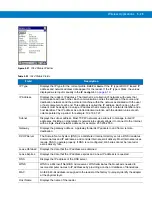
Страница 228: ...ville New York 11742 USA 1 800 927 9626 http www symbol com MOTOROLA and the Stylized M Logo and Symbol and the Symbol logo are registered in the U S Patent and Trademark Office All other product or service names are the property of their registered owners Motorola Inc 2008 ...

Отзывы: