


PTP 250 User Guide
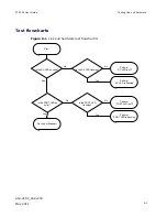
Testing link end hardware
phn-2182_002v000
May 2011
8-11
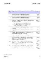
Table 8-1
RJ45 cable resistance tests at the PoE power supply end
Step
Test
Result
1
Measure the resistance between pins 1 and 2.
Ohms
2
Measure the resistance between pins 3 and 6.
Ohms
3
Measure the resistance between pins 4 and 5.
Ohms
4
Measure the resistance between pins 7 and 8.
Ohms
5
Ensure that all the results of steps 1 to 4 are within 10%
of each other as follows:
Take the minimum result and multiply by 1.1.
If any of the remaining steps 1 to 4 results are
greater than this, the test has failed.
PASS or
FAIL
6
Measure the resistance between pins 1 and 3. Subtract
0.2 Ohms.
Ohms
7
Measure the resistance between pins 4 and 7. Subtract
0.8 Ohms.
Ohms
8
Compare the results of steps 1 to 4 and steps 6 to 7 to
the maximum allowed, that is 20 Ohms.
If any of the steps 1 to 6 results are greater than the
maximum allowed, the test has failed.
PASS or
FAIL
9
Measure the resistance between pin 1 and the screen
(ODU ground). If it is less than 100K ohms (regardless
of cable length), the test has failed.
K Ohms
PASS or
FAIL
10
Measure the resistance between pin 8 and the screen
(ODU ground). If it is less than 100K ohms (regardless
of cable length), the test has failed.
K Ohms
PASS or
FAIL
11
Measure the resistance between pin 1 and pin 8. If it is
less than 100K Ohms (regardless of cable length), the
test has failed.
K Ohms
PASS or
FAIL
Содержание Motorola PTP 250
Страница 20: ...List of Tables phn 2182_002v000 xiv May 2011 ...
Страница 30: ......
Страница 80: ...Data network planning Chapter 2 Planning considerations phn 2182_002v000 2 22 May 2011 ...
Страница 126: ...Notifications Chapter 4 Reference information phn 2182_002v000 4 36 May 2011 ...
Страница 192: ...Connecting link to the network Chapter 6 Configuration and alignment phn 2182_002v000 6 36 May 2011 ...
Страница 234: ...Testing the radio link Chapter 8 Troubleshooting phn 2182_002v000 8 14 May 2011 ...