


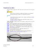


PTP 250 User Guide
Installing the drop cable and LPU
phn-2182_002v000
May 2011
5-19
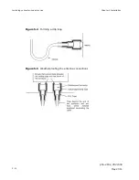
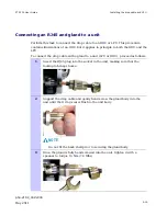
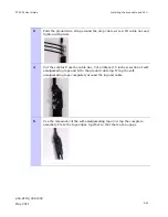
Connecting an RJ45 and gland to a unit
Perform this task to connect the drop cable to an ODU or LPU. This procedure
contains illustrations of an ODU, but it applies in principle to both the ODU and the
LPU.
To connect the drop cable with a gland to a unit (LPU or ODU), proceed as follows:
1
Insert the RJ45 plug into the socket in the unit, making sure that the
locking tab snaps home.
2
Support the drop cable and gently hand screw the gland body into the
unit until the O ring seal is flush to the unit body.
NOTE
Do not fit the back shell prior to securing the gland body.
3
Once the gland is fully hand screwed into the unit, tighten it with a
spanner to torque 10 Nm (7.4 ftlbs).
Содержание Motorola PTP 250
Страница 20: ...List of Tables phn 2182_002v000 xiv May 2011 ...
Страница 30: ......
Страница 80: ...Data network planning Chapter 2 Planning considerations phn 2182_002v000 2 22 May 2011 ...
Страница 126: ...Notifications Chapter 4 Reference information phn 2182_002v000 4 36 May 2011 ...
Страница 192: ...Connecting link to the network Chapter 6 Configuration and alignment phn 2182_002v000 6 36 May 2011 ...
Страница 234: ...Testing the radio link Chapter 8 Troubleshooting phn 2182_002v000 8 14 May 2011 ...