HARDWARE PREPARATION AND INSTALLATION
M68HC11EVB/D
2-7
7
2.3.6
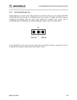
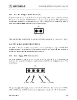
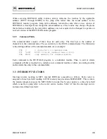
Host Port RX Signal Disable Header (J6)
Jumper header J6 is used to disable the host computer I/O port RX output signal line (connector
P3, pin 2) when using the EVB MCU SCI in a target system application. When performing a
downloading operation or communicating to a host computer in the transparent mode, a
fabricated jumper is installed on pins 1 and 2 as shown below.
J6
1 2
Signal disabling is accomplished by the removal of the fabricated jumper installed on pins 1 and 2.
2.4 INSTALLATION INSTRUCTIONS
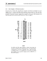
The EVB is designed for table top operation. A user supplied power supply and RS-232C
compatible terminal are required for EVB operation. An RS-232C compatible host computer is
optional for downloading user assembled code to the EVB.
2.4.1
Power Supply - EVB Interconnection
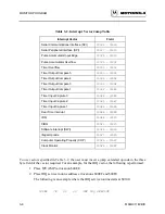
The EVB re5 Vdc @ 0.5 A, +12 Vdc @ 0.1 A, -12 Vdc @ 0.1 A, and GND for
operation. Interconnection of the power supply wiring to the EVB power supply connector P4 is
shown below.
P4
1
2
3
4
-12 VDC GND +5 VDC +12 VDC
The power supply cable simply consists of four 14-22 AWG wires that interconnect -12 VDC,
GND, +5 VDC, and +12 VDC, from the user supplied power supply to the EVB connector P4.
Содержание M68HC11EVB
Страница 9: ...CONTENTS x M68HC11EVB D ...
Страница 35: ...MONITOR PROGRAM 3 8 M68HC11EVB D ...
Страница 81: ...OPERATING INSTRUCTIONS 4 46 M68HC11EVB D ...
Страница 97: ...SUPPORT INFORMATION 6 12 M68HC11EVB D Figure 6 3 EVB Schematic Diagram Sheet 2 of 2 ...
Страница 103: ...APPLICATIONS B 2 M68HC11EVB D Figure B 1 Single Chip Mode Configuration ...


