HARDWARE PREPARATION AND INSTALLATION
2-4
M68HC11EVB/D
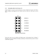
2.3.3
Memory Select Headers (J3 and J7)
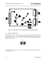
Jumper headers J3 and J7 are used to configure the EVB circuitry for an additional 8k memory
device (e.g., MCM6164) installed at location U4. This device is provided by the user if required.
If a RAM device is installed at location U4, a fabricated jumper is installed on pins 1 and 2 of
jumper header J3 or J7 as shown below.
J3 J7
1 2
1 2
NOTE
Jumper headers J3 and J7 should not have fabricated jumpers
installed at the same time.
Jumper header J7 is for factory use only.
Jumper header J3 or J7 applies a chip enable (CE*) signal to the RAM device installed at location
U4. The RAM device is selected or deselected by the installation of a fabricated jumper on either
jumper header J3 or J7. If the installed RAM device is not required, but left installed, both jumper
headers J3 and J7 should not have fabricated jumpers installed.
Installing a fabricated jumper on jumper header J3 causes the memory device at location U4 to be
mapped at locations $6000 to $7FFF. Installing a fabricated jumper on jumper header J7 causes
the memory device located at location U4 to be mapped at locations $A000 to $BFFF.
NOTE
MCU EEPROM may be located at $B600 to $B7FF.
Содержание M68HC11EVB
Страница 9: ...CONTENTS x M68HC11EVB D ...
Страница 35: ...MONITOR PROGRAM 3 8 M68HC11EVB D ...
Страница 81: ...OPERATING INSTRUCTIONS 4 46 M68HC11EVB D ...
Страница 97: ...SUPPORT INFORMATION 6 12 M68HC11EVB D Figure 6 3 EVB Schematic Diagram Sheet 2 of 2 ...
Страница 103: ...APPLICATIONS B 2 M68HC11EVB D Figure B 1 Single Chip Mode Configuration ...


