HARDWARE PREPARATION AND INSTALLATION
M68HC11EVB/D
2-1
1
CHAPTER 2
HARDWARE PREPARATION AND INSTALLATION
2.1 INTRODUCTION
This chapter provides unpacking instructions, hardware preparation, and installation instructions
for the EVB.
2.2 UNPACKING INSTRUCTIONS
After unpack EVM from shipping carton, refer to the packing list and verify that all items are
present. Save packing material for storing or reshipping the EVM.
2.3 HARDWARE PREPARATION
This section describes the inspection/preparation of EVB components prior to target system
installation. This description ensures that the EVB components are properly configured for target
system operation. The EVB has been factory-tested and is shipped with factory-installed jumpers.
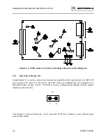
Inspect the EVB for jumper placements prior to target system installation. Figure 2-1 illustrates
the EVB connector, switch, and jumper header locations.
Use connector P1 to connect the EVB to the target system. Use connectors P2 and P3 to connect
the EVB to the external terminal and host computer equipment, respectively. Use connector P4 to
connect an external power supply to the EVB. Use switch S1 to reset the EVB. Jumper header
locations J1 through J7 provide these capabilities:
•
Reset select (J1)
•
Clock select (J2)
•
Memory select (J3 and J7)
•
Program execution select (J4)
•
Terminal baud rate select (J5)
•
Host port RX signal disable (J6)
Содержание M68HC11EVB
Страница 9: ...CONTENTS x M68HC11EVB D ...
Страница 35: ...MONITOR PROGRAM 3 8 M68HC11EVB D ...
Страница 81: ...OPERATING INSTRUCTIONS 4 46 M68HC11EVB D ...
Страница 97: ...SUPPORT INFORMATION 6 12 M68HC11EVB D Figure 6 3 EVB Schematic Diagram Sheet 2 of 2 ...
Страница 103: ...APPLICATIONS B 2 M68HC11EVB D Figure B 1 Single Chip Mode Configuration ...


