S P E C T R U M E n t e r p r i s e M a n a g e r
M o t o r o l a V a n g u a r d D e v i c e s
8 of 95
Figure 1
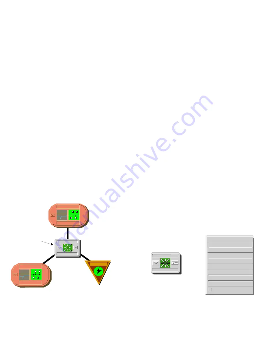
shows a portion of a Topology view in
which the Device icon representing the
MotMPRouter model appears surrounded by
icons representing the network entities which the
device connects—in this case two Ethernet LANs
and an Off-Page Reference icon representing a
Wide Area Link to a corporate network.
Figure 1:
MotMPRouter Device Icon in
Topology View
Device icons provide access to the views,
subviews, and tables that let you manage the
modeled device.
Figure 2
shows the model-
specific portion of the
Icon Subviews
menu for a
MotMPRouter Device icon in a Topology view. The
views listed below are accessible directly from this
menu and are described individually in
subsequent sections of this documentation.
•
Device Views (Page 9)
•
Device Topology Views (Page 16)
•
Application View (Page 18)
•
Performance Views (Page 61)
•
Configuration Views (Page 63)
•
Model Information Views (Page 87)
Figure 2:
Device Icon Subviews Menu Options
Admin_Nashua
LAN 802.3
Sales_Nashua
LAN 802.3
Device Icon
JK2
MotMPRouter
WA_Link
Zoom
- >
Device
DevTop
Application
Configuration
Model Information
Primary Application
Flash Green Enabled
Device Performance
JK2
MotMPRouter
Acknowledge


