


DSP 2x400 PS-PL
REV.1-02/11
M
1.5
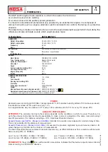
TECHNICAL DATA
28/11/05 78413-GB
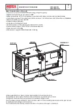
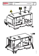
The DSP 2x400 engine driven welder ia a unit which ensures the function as:
a) a current source for arc welding
b) a current source for the auxiliary power generation
It is meant for industrial and professional use, powered by an endothermic engine; it is composed of
various main parts such as: engine, alternator, electric and electronic controls, the fairing or a protective
structure.
The assembling is made on a steel structure, on which are provided elastic support which must damp the
vibrations and also eliminate sounds which would produce noise.
Technical data
DSP 2x400 PS-PL
GENERATOR
Output three-phase
40 kVA / 400 V / 57.8 A
Output single-phase
20 kVA / 230 V / 87 A
Frequency
50 Hz
Cos
ϕ
0.8
ALTERNATOR
Self-excited, self-regulated, brushless
Type
three-phase, asynchronous
Insulating class
H
ENGINE
Mark / Model
PERKINS / 1103C-33TG3
Type / Cooling system
Diesel 4-Stroke / water
Cylinders / Displacement
3 / 3300 cm
3
Net output
45.6 kW (62 HP)
Speed
1500 rpm
Fuel consumption (welding 60%)
6.7 l/h
Cooling system capacity
10.2 l
Engine oil capacity
7.9 l
Starter
Electric
GENERAL SPECIFICATIONS
Battery
12V - 100Ah
Tank capacity
102 l
Running time (welding 60%)
15 h
Protection
IP 44
Dimensions Lxwxh (mm) *
2490x1030x1480
Weight *
1300 Kg
Measured acoustic power LwA (pressure LpA)
89 dB(A) (64 dB(A) @ 7 m)
Guaranteed acoustic power LwA (pressure LpA)
90 dB(A) (65 dB(A) @ 7 m)
* Dimensions and weight are inclusive of all parts without wheels and towbar.
2000 / 14 / CE
POWER
Declared power according to
ISO 3046-1 (temperature 25°C, 30% relative humidity, altitude 100 m above sea level).
It’s admitted overload of 10% each hour every 12 h.
In an approximative way one reduces: of 1% every 100 m altitude and of 2.5% for every 5°C above 25°C.
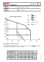
ACOUSTIC POWER LEVEL
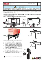
ATTENTION
:
The concrete risk due to the machine depends on the conditions in which it is used. Therefore, it is
up to the end-user and under his direct responsibility to make a correct evaluation of the same risk and to adopt
specific precautions (for instance, adopting a I.P.D. -Individual Protection Device)
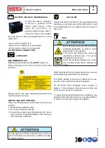
Acoustic Noise Level (L
WA
) - Measure Unit dB(A):
it stands for acoustic noise released in a certain delay of time.
This is not submitted to the distance of measurement.
Acoustic Pressure (Lp) - Measure Unit dB(A):
it measures the pressure originated by sound waves emission. Its
value changes in proportion to the distance of measurement.
The here below table shows examples of acoustic pressure (Lp) at different distances from a machine with Acoustic
Noise Level (L
WA
) of 95 dB(A)
Lp a 1 meter = 95 dB(A) - 8 dB(A) = 87 dB(A)
Lp a 7 meters = 95 dB(A) - 25 dB(A) = 70 dB(A)
Lp a 4 meters = 95 dB(A) - 20 dB(A) = 75 dB(A)
Lp a 10 meters = 95 dB(A) - 28 dB(A) = 67 dB(A)
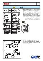
PLEASE NOTE:
the symbol when with acoustic noise values, indicates that the device respects noise emission
limits according to 2000/14/CE directive.
2000 / 14 / CE
Содержание DSP 2x400 PS-PL
Страница 38: ...DSP 2x400 PSX REV 0 11 05 M 53 Dimensioni Abmessungen Dimension 18 11 05 88412 I...
Страница 42: ...DSP 2x400 PS PL REV 0 11 05 M 61 2 Stromlaufplan 28 11 05 78413 D...
Страница 43: ...DSP 2x400 PS PL REV 1 02 11 M 61 3 Stromlaufplan 28 11 05 78413 D...
Страница 44: ...DSP 2x400 PS PL REV 1 02 11 M 61 4 Stromlaufplan 28 11 05 78413 D...
Страница 45: ...DSP 2x400 PS PL REV 1 02 11 M 61 5 Stromlaufplan 28 11 05 78413 D...
Страница 46: ...DSP 2x400 PS PL REV 1 02 11 M 61 6 Stromlaufplan 28 11 05 78413 D...


