


TROUBLE SHOOTING
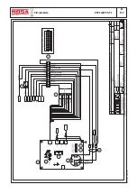
DSP - EP5/EP7/ES
M
40.2
18/1
1/05 M40DSP/EP5-ES_GB
REV.3-09/07
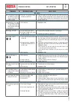
PROBLEM
POSSIBLE CAUSE
WHAT TO DO
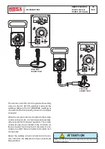
WELDING WITH V.R.D.
P10
The welding tension after
3 sec isn’t less enough
(plus in 12V dc)
1) Net R.C. defective or disconnected
from + or - welding socket
2) WDC defective.
1)
Check the net R.C. Check the connections.
2)
Replace
the WDC.
GENERETING
P1
Voltmeter shows no volta-
ge or low voltage but ac-
tual voltage at the sockets
is OK.
1) Voltmeter malfunction
1)
Replace
the voltmeter.
P2
No three-phase voltage
present at the socket(s).
1) Differential switch not inserted
2) Differential switch malfunction
1)
Turn on
the switch.
2)
Replace
the
switch.
P3
No single
phase voltage
one socket but voltmeter
reading is normal and
there is voltage on the
other sockets.
1) Intervention of thermal switch due
to excessive current.
2) Thermal switch malfunction.
1)
Push in
the thermal switch.
2)
Replace
the thermal switch.
P4
No voltage present.
(See problem P9)
1) Short circuit present on the gene-
rator outputs.
1)
Disconnect
all outputs on the generator except for those on the con-
densers and re-start machine; check for voltage on condensers.
MOTOR
P1
The engine does not start
or stops immediately after
startup.
1) Low battery voltage, battery dead
or defective.
2) Presence of air in the fuel supply
circuit.
3) Circuit breaker engine protection
4) Engine solenoid
1)
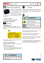
Check the warning light “state of the battery”: - Green colour: battery
OK - Black colour: battery to be recharged - White colour: battery to be
replaced -
DO NOT OPEN THE BATTERY.
2) Carry out de-aeration on the fuel system. See engine operating manual.
3) Insert the circuit breaker. In case the problem persists, check the electrical
circuit and eliminate the problem. Call an authorised service centre.
4) See engine manual
P2
Engine stops due to
intervention of EP5/EP7/
ES.
1) Engine temperature too high or
insufficient oil pressure.
2) High temperature sensor or oil
pressure defective.
3) EP5/EP7/ES protection defective
1)
Check
oil level.
2)
Replace
the malfunctioning sensor.
3)
Replace
the protection.
P3
The battery is not
charged.
1) Battery charger alternator defecti-
ve.
2) Battery charger warning light de-
fective.
1)
Replace
2)
Replace
P4
For other problems, refer
to the attached engine
manual
Содержание DSP 2x400 PS-PL
Страница 38: ...DSP 2x400 PSX REV 0 11 05 M 53 Dimensioni Abmessungen Dimension 18 11 05 88412 I...
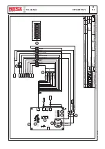
Страница 42: ...DSP 2x400 PS PL REV 0 11 05 M 61 2 Stromlaufplan 28 11 05 78413 D...
Страница 43: ...DSP 2x400 PS PL REV 1 02 11 M 61 3 Stromlaufplan 28 11 05 78413 D...
Страница 44: ...DSP 2x400 PS PL REV 1 02 11 M 61 4 Stromlaufplan 28 11 05 78413 D...
Страница 45: ...DSP 2x400 PS PL REV 1 02 11 M 61 5 Stromlaufplan 28 11 05 78413 D...
Страница 46: ...DSP 2x400 PS PL REV 1 02 11 M 61 6 Stromlaufplan 28 11 05 78413 D...


