Mosa DSP 2x400 PS-PL Скачать руководство пользователя страница 42

DSP 2x400 PS-PL

REV.0-11/05

M

61.2

Stromlaufplan

28/1

1/05 78413-D

Содержание DSP 2x400 PS-PL

Страница 1: ...DSP 2x400 PS PL 784139003 GB 0 2 1 1 28 11 05 78413M00 preparato da UPT approvato da DITE USE AND MAINTENANCE MANUAL...

Страница 2: ...ACHINE DSP 2x400 PSX DSP 2x400 PS PL M 0 REV 0 02 11 Main Characteristics of the unit Control of current with CHOPPER technology at high frequency Digital control technique by means of DSP Major produ...

Страница 3: ...isfy the needs of its clients aswell as to improve the transparency and thecom munications regarding all the company s activesin accordance with the official procedures and inhar mony with the MOSA Ma...

Страница 4: ...DVICE BEFORE USE M 2 6 INSTALLATION AND ADVICE M 3 UNPACKING M 4 2 TRANSPORT AND DISPLACEMENTS COVERED UNITS M 6 8 ASSEMBLY CTL M 20 PREPARING THE UNIT M 21 START UP M 22 SHUTTING DOWN THE MOTOR M 31...

Страница 5: ...aws in force in the matter In no case MOSA division of B C S S p A will be held responsible for any damaga direct or indirect in relation with the use of the given information MOSA division of B C S S...

Страница 6: ...aces protected from dampness and heat You must take into account that some figures contained in it want only to identify the described parts and therefore might not correspond to the machine in your p...

Страница 7: ...of the declaration of conformity included in any machine standard equipment Here below the adopted symbol CE marking is clearly readable and unerasable and it can be either part of the data plate A o...

Страница 8: ...ola Serial number ______________________________ conforme con quanto previsto dalle Direttive Comunitarie e relative modifiche est en conformit avec ce qui est pr vu par les Directives Communautaires...

Страница 9: ...A 64 dB A 7 m Guaranteed acoustic power LwA pressure LpA 90 dB A 65 dB A 7 m Dimensions and weight are inclusive of all parts without wheels and towbar 2000 14 CE POWER Declared power according to ISO...

Страница 10: ...lding and Generation can be used simultaneously however the engine cannot be overloaded The table below gives the maximum limits to be respected STATIC CHARACTERISTIC 100 200 300 400 500 A V 10 20 30...

Страница 11: ...harm to persons or things Do not use without protective devices provided Removing or disabling protective devices on the machine is prohibited Do not use the machine if it is not in good technical co...

Страница 12: ...persons Use only with safety clothing It is compulsory to use the personal protection means given in equip ment Use only with safety clothing It is compulsory to use the personal protection means giv...

Страница 13: ...completely Wipe up spilled fuel before starting engine An electric shock can kill Shut off fuel of tank when moving machine where it is assembled Avoid spilling fuel on hot engine Sparks may cause th...

Страница 14: ...at the area is safe before starting any welding operation Do not touch any bare wires leads or contacts as they may be live and there is danger of electric shock which can cause death or serious burns...

Страница 15: ...so as to cause a dangerous increase of the temperature Make sure that the machine does not move during the work block it possibly with tools and or devices made to this purpose Maximum leaning of the...

Страница 16: ...Installazione Installation Installation Luftzirkulation 18 11 05 88412 I REV 1 09 08 DSP 2x400 PSX M 2 7 M1 4 90 M1 4 A...

Страница 17: ...en rough handling or taking away of parts contained inside the packing or in the set In case you find damages rough handling or absence of parts envelopes manuals etc we advise you to inform immediate...

Страница 18: ...did not keep to the instructions you could damage the structure of the machine die Wartung durchfuhrt Motor abstellen bevor man d effectuer toute manutention Arreter le moteur avant Fermare il motore...

Страница 19: ...machine to the ground and place the parking foot definitively regulating at the best height ATTENTION Do not substituite the original tires with other types ATTENTION 7 8 9 CTL 35 50 CTL 45 COMANDS 5...

Страница 20: ...he state of the battery from the colour of the warning light which is in the upper part Green colour battery OK Black colour battery to be recharged White colour battery to be replaced DO NOT OPEN THE...

Страница 21: ...t an easy job A lack in tacking these precautions would result in the mix of different additives used in different coolants which would originate gelatinous substances capable of obstructing the cooli...

Страница 22: ...M5 2 yellow Battery charge M5 3 red Overspe ed M5 4 red High tem perature M5 5 red Low oil pressure M5 6 green Protec tion unit on M5 5 M5 6 M5 4 M5 3 M5 2 M5 1 M STOP OFF b a c LOW OIL PRESSURE M5 5...

Страница 23: ...PING THE ENGINE 28 11 05 88412 GB Before stopping the engine it is compulsory to disconnect or shut off any loads which are connec ted to the unit auxiliary outputs stop welding To stop the engine Tur...

Страница 24: ...te Welding selector mode Welding ammeter Welding current regulator Welding voltage voltmeter Polarity inverter control Remote control socket Prise de soudage Prise de soudage Prise de mise terre Prise...

Страница 25: ...r is suitable for use in environments with an increased risk of electrical shock WELDING CABLE CONNECTION Fully insert the welding cable plugs into the corresponding sockets turning them clockwise to...

Страница 26: ...age adjusting knob to the minimum setting SETTING THE WELDING PROCESS 11 10 04 M33_WDC_GB CV CC STAND BY CONTACT STARTING REMOTE CONTROL 70 20 25 40 100 WELDING DIGITAL CONTROL 130 160 190 220 250 280...

Страница 27: ...the alternator fan will help cool down the chopper more quickly After a few minutes the LED will automatically switch itself off and the welding voltage current will once again be available at the plu...

Страница 28: ...ow mentioned table WARNING A electric ground B C 5 V d c D E F 5 V d c G H welding ground I 44 48V a c J 44 48V a c DESCRIPTION To potentiometer RC1 terminal a To potentiometer RC1 central b To potent...

Страница 29: ...hould intervene again replace it with another one with matching intervention current specifications and or contact the Service Depart ment Note do not forcibly hold the central button of the thermal p...

Страница 30: ...te control connector 8 it is functional and automati cally excludes the front panel regulation The remote control can also be connected to the connector on the wire feeder front panel but in this case...

Страница 31: ...1 WDC defective 2 Chopper defective 3 Current sensor defective 1 Switch off the machine and start it up again if the LED remains off try to weld verifying that the welding is regular if the LED light...

Страница 32: ...outputs on the generator except for those on the con densers and re start machine check for voltage on condensers MOTOR P1 The engine does not start or stops immediately after startup 1 Low battery vo...

Страница 33: ...tiometer of the WDC works correctly perform the following test 1 Start the welding machine and let it run at nominal r p m 2 Connect a multimeter set for VDC mea surement between pins 1 GND and 12 of...

Страница 34: ...DRAWING 5 DRAWING 4 Put the knob on RC1 at minimum max put one ohmmeter from pin A B and measure the resistance Knob Resistance Minimum Max 50 100 4 5 4 7 K P1 Supply connector P2 Chopper connector P...

Страница 35: ...ce and troubleshooting work l Stop the engine before doing any work inside the machine If for any reason the machine must be operated while working inside pay attention moving parts hot parts exhaust...

Страница 36: ...the covers and all the other parts of the machine carefully Protect the machine with a plastic hood and store it in o dry place DIESEL ENGINE For short periods of time it is advisable about every 10...

Страница 37: ...d of the various components of the machine must be made accordingly to rules in force of law a o local rules Particular attention must be paid when getting rid of lubricating oils battery electrolyte...

Страница 38: ...DSP 2x400 PSX REV 0 11 05 M 53 Dimensioni Abmessungen Dimension 18 11 05 88412 I...

Страница 39: ...holder ground clamp Special for steels run on pipes with R max 55 kg mm2 Weld in all position volatile slag ELECTRODES IDENTIFICATION ACCORDING TO A W S STANDARDS E X X Y Z 2 digits type of coating an...

Страница 40: ...ke solenoid O4 Step relay P4 Circuit breaker Q4 Battery charge sockets R4 Sensor cooling liquid temperature S4 Sensor air filter clogging T4 Warning light air filter clogging U4 Polarity inverter remo...

Страница 41: ...di legge la proprieta del presente disegno con divieto di riprodurlo o comunicarlo a terzi senza sua autorizzazione M5 15 b2 a2 24 22 18 a1 b1 21 25 230V 50 60Hz 11 1 4 3 1 2 1 1 1 2 F3 1 2 L5 3 52 5...

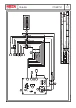
Страница 42: ...DSP 2x400 PS PL REV 0 11 05 M 61 2 Stromlaufplan 28 11 05 78413 D...

Страница 43: ...DSP 2x400 PS PL REV 1 02 11 M 61 3 Stromlaufplan 28 11 05 78413 D...

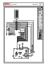
Страница 44: ...DSP 2x400 PS PL REV 1 02 11 M 61 4 Stromlaufplan 28 11 05 78413 D...

Страница 45: ...DSP 2x400 PS PL REV 1 02 11 M 61 5 Stromlaufplan 28 11 05 78413 D...

Страница 46: ...DSP 2x400 PS PL REV 1 02 11 M 61 6 Stromlaufplan 28 11 05 78413 D...

Отзывы: