background image

9

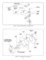
FIGURE 4 - CABLE CONNECTIONS, CONTROL END

FIGURE 5 - SIDE MOUNT, INSTALLATION

Содержание SL-3

Страница 1: ...ion and maintenance instructions for your Morse marine product Please read these Instructions through carefully and entirely before beginning Installation All specifications and features are subject to change without notice 2006 Teleflex Marine 212442 Rev 1 Marine Products SL 3 Engine Controls Owner s Manual ...

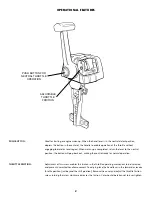
Страница 2: ... control ready for normal operation THROTTLE FRICTION Adjustment of this screw enables the friction in the throttle operating mechanism to be increased and prevent unwanted handle movement To adjust place the hand lever in the forward or reverse throttle position just beyond the shift position Remove the cover and adjust the throttle friction screw turning the screw clockwise increases the frictio...

Страница 3: ...NOT HAZARD RELATED WARNING CAUTION STANDARD CONTROL FEATURES SINGLE LEVER OPERATION NEUTRAL THROTTLE WARM UP NEUTRAL SAFETY SWITCH TO PREVENT STARTING IN GEAR THREE POSITION SHIFT ARM TO PROVIDE 3 TRAVEL OPTIONS FRICTION DAMPER TO PREVENT THROTTLE CREEP IMPORTANT SAFETY NOTICES TELEFLEX MARINE RECOMMENDS THE USE OF AN EMERGENCY SHUT OFF SWITCH AS AN ADDED SAFETY MEASURE THE SWITCH IS DESIGNED SOLE...

Страница 4: ...bles or two 2 each OMC BRP OEM type cables or two 2 each Mercury Mariner Force OEM type cables One for throttle and one for shift 2 Throttle and Shift Connection Kits for engine See Teleflex Catalog contact your nearest Teleflex dealer TOOLS NEEDED FOR INSTALLATION ...

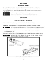
Страница 5: ...E MEASUREMENT AND ROUTING 2 1 Measure from the Control position along an unobstructed path to the shift and throttle connections 2 2 Cables lengths are measured from end to end When a measurement is in feet and inches specify the next whole foot FOR OUTBOARD ENGINES ADD FOUR 4 FEET 1 25 M TO THE LENGTH OF THE CABLE FOR A LOOP TO ALLOW FOR ENGINE SWING 2 3 The Cable runs should minimize the number ...

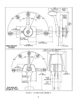
Страница 6: ...6 FIGURE 2 CONTROL MEASUREMENTS ...

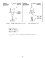
Страница 7: ...E END FITTING TO HOLE 4 ON LEVER CABLES AND WIRING SHOULD BE PRE INSTALLED ON CONTROL BEFORE FINAL MOUNTING IS MADE FIGURE 3a CONTROL CABLE CONNECTING POINTS BY SHIFT ACTUATION TYPE OMC BRP applications would include Outboards Evinrude and Johnson I Os Stern Drives OMC some Volvo Mercury applications would include Outboards Mercury Mariner most Force I Os Stern Drives MerCruiser Inboards Mercury a...

Страница 8: ... Johnson I Os Stern Drives OMC some Volvo Mercury applications would include Outboards Mercury Mariner most Force I Os Stern Drives MerCruiser Inboards Mercury and MerCruiser Where a particular engine brand is noted in the illustrations above those cable mounting locations are for OEM type cables not the universal 3300 33C type ...

Страница 9: ...9 FIGURE 4 CABLE CONNECTIONS CONTROL END FIGURE 5 SIDE MOUNT INSTALLATION ...

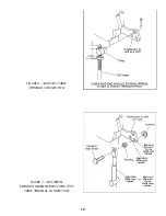
Страница 10: ...10 FIGURE 6 3300 33C CABLE TERMINAL CONNECTION FIGURE 7 OMC BRP MERCURY MARINER FORCE OEM TYPE CABLE TERMINAL CONNECTION ...

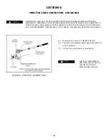
Страница 11: ...NTROL MAY NOT FUNCTION PROPERLY AND DAMAGE TO THE CONTROL THE CABLE AND OR MOTOR COULD RESULT SECTION 4 THROTTLE CABLE CONNECTION ENGINE END 4 1 Make sure the Control is in NEUTRAL DETENT 4 2 The Fuel Lever should rest lightly against the Idle Stop on the carburetor 4 3 Connect the Throttle Cable to the fuel lever THROTTLE CABLE MUST BE FREE WHEN FUEL LEVER IS IN THE IDLE POSITION TO PREVENT HARD ...

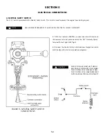
Страница 12: ...nd one wire to the NO Normally Open Terminal The test light MUST light 6 2 Connect the Neutral Safety Switch between the ignition switch start lead and the starter solenoid see diagram CHECK TO MAKE SURE THAT THERE IS ELECTRICAL CONTINUITY ONLY WHEN THE CONTROL IS IN NEUTRAL WHEN THE CONTROL IS IN GEAR THERE MUST NOT BE ANY ELECTRICAL CONTINUITY USE A BATTERY POWERED TEST LIGHT OR TEST METER TO CH...

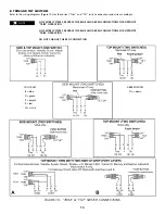
Страница 13: ...D GREEN CONNECTIONS FOR OPPOSITE TRIM OPERATION DO NOT CHANGE THE RED CONNECTION B TRIM AND TILT SWITCHES Refer to the wiring diagrams Figure 10 for the correct Trim and Tilt switch connections and wire accordingly COLOR KEY B blue G green P purple R red W white ABBREVIATION Dn down FIGURE 10 TRIM TILT SWITCH CONNECTIONS NOTE ...

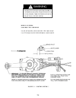
Страница 14: ...UNCTION WITH THE ENGINE MANUFACTURERS RECOMMENDATIONS MAY RESULT IN LOSS OF SPEED CONTROL WARNING MORSE SL 3 CONTROL ALL MODELS TOP SIDE MOUNT ON ANY INSTALLATION USING A 3300 33C TYPE CABLE OR ANY S A E TYPE CABLE FOLLOW THE PROCEDURE AS SHOWN BELOW FIGURE 11 CONTROL DETAILS ...

Страница 15: ...ount Tilt Switch wire harness 309514 Lanyard for Cut off Switch side mount 311376 Cut off Switch w Cover side mount Outboards only 311380 002 Cut off Switch Only side mount Outboards only 311379 002 Cut off Switch w Cover side mount Inboards and Stern Drives I Os 311380 001 Cut off Switch Only side mount Inboards and Stern Drives I Os 311379 001 Neutral Safety Switch 051801 033 REPLACEMENT PARTS K...

Страница 16: ...oat combination where the engine horsepower exceeds the rating established by the boat manufacturer has been used with other product s which in Teleflex Marine s opinion are incompatible with the Teleflex Marine product THE EXPRESS WARRANTY SET FORTH ABOVE IS IN LIEU OF ALL OTHER WARRANTIES EXPRESS OR IMPLIED INCLUDING BUT NOT LIMITED TO THE IMPLIED WARRANTIES OF MERCHANTABILITY AND FITNESS FOR A PA...

Отзывы: