5
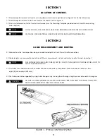
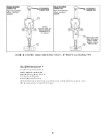
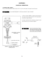
FIGURE 1 - TYPICAL CONTROL SYSTEMS
SECTION 1
LOCATION OF CONTROL
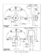
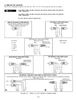
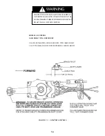
1.1 Allow adequate clearance for Hand Lever swing (forward and reverse positions). See Figure 2 for Control dimensions.
1.2 Allow adequate clearance under the console for the Cables. Refer to Figure 2.
1.3 After a suitable location for the Control is determined, use the Mounting Template provided and cut & drill the mounting
holes
required.
ON ALL MODELS, THE COVER WILL HAVE TO BE REMOVED TO EXPOSE THE MOUNTING HOLES.
SEE FIGURE 5 FOR ADDITIONAL SIDE MOUNT MODEL INSTALLATION INFORMATION.
CAUTION
SECTION 2
CABLE MEASUREMENT AND ROUTING
2.1 Measure from the Control position along an unobstructed path to the shift and throttle connections.
2.2 Cables lengths are measured from end to end. When a measurement is in feet and inches, specify the next whole foot.
FOR OUTBOARD ENGINES, ADD FOUR (4) FEET (1.25 M) TO THE LENGTH OF THE CABLE FOR A LOOP TO
ALLOW FOR ENGINE SWING.
2.3 The Cable runs should minimize the number of bends and avoid any sharp bends. Make no bends in Cables less than
eight (8) inches radius (203 mm).
2.4 The Cables should be supported by using Cable Hangers or by running them through straight sections of conduit for long runs.
DO NOT USE CABLE HANGERS OR CLAMPS WHICH MAY CRUSH OR STRESS THE CABLES IN ANY WAY.
DOING SO MAY IMPAIR THE FUNCTION OF THE CABLE.
NOTE
NOTE
NOTE


