


8
Morley-IAS
996-203-000-2, Rev. 02
3.2
Installing the Enclosure (Surface Mount)
-
Using the supplied key open the main door to access the enclosure interior.
-
Disconnect the ribbon cable to the Display PCB at the Base PCB (this cable cannot be disconnected
at the Display PCB).
-
Remove the front cover as follows: with the door at an angle to the enclosure of between 30° and
40°, carefully lift it clear of the two hinge pins - DO NOT force it. If the door does not move up easily,
the angle is too small or too large, so adjust the angle in either direction until the door lifts easily.
-
If the medium enclosure is to be installed remove the lower cover by moving upwards and pull away.
This cannot be removed with the main cover
in situ
.
-
The Base card or PSU do not need to be removed from the enclosure if the provided knockouts are
to be used. If additional access holes are to be made it is recommended that the Base PCB and PSU
are removed to avoid inadvertant damage or contamination.
-
Remove the necessary knockouts for the installation cabling.
-
Mount the enclosure in the desired location using all three mounting holes A (small enclosure) or B
(medium enclosure).
-
Use a drill bit diameter 7.0 mm and a suitable 40 mm long expansion plug. Fix the panel to the wall
with No. 10 screws length 1½” or M5 screws length 40 mm.
-
Install the external wiring into the enclosure using the appropriate glands/ conduit fittings.
-
Sufficient knockouts are provided at the top of the enclosure. Refer to wiring sections for recommended
positions.
-
If you punch out other holes, be sure that they do not interfere with any component mounting positions.
-
Use a brush to clean any dust and swarf from inside the enclosure before re-fitting the main door.
To avoid distortion of the back box when preparing knockouts, place the appropriate back
box face on a supporting surface (e.g. work bench)
.
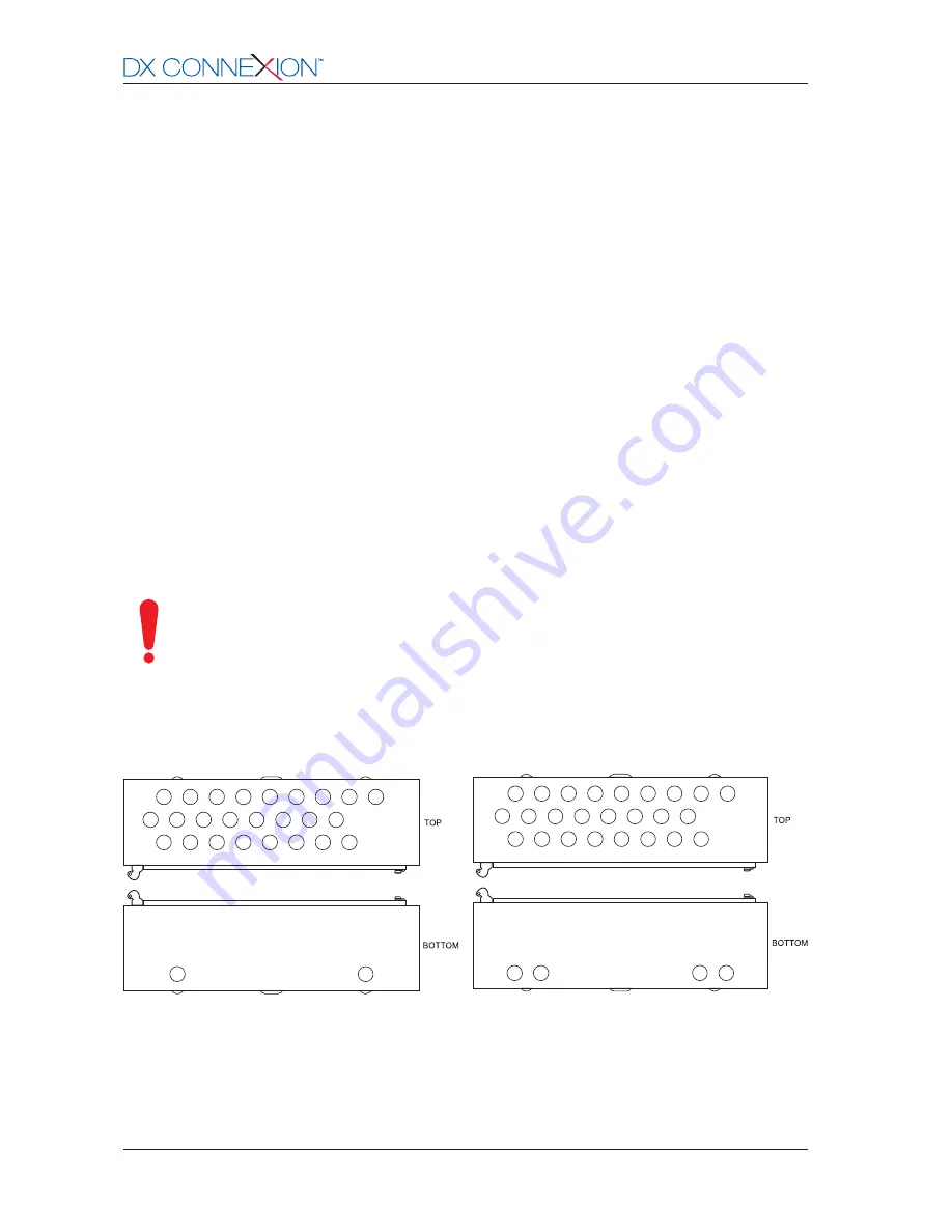
3.2.1 Position of Knockouts
-
20mm knockouts are provided on the top and bottom faces of the enclosures as shown below:
DXc1 Panel
DXc2/4 Panels
Figure 3 - Position of Knockouts
www.acornfiresecurity.com
www.acornfiresecurity.com


