background image

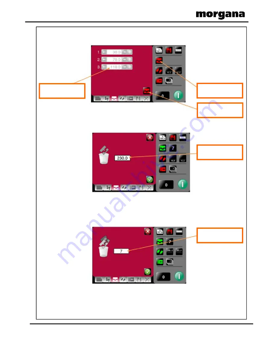
Greyed out area indicates
the trim is not selectable

Status shows creasing off

icon

This button toggles

creasing on & off.

Crease 230 mm from lead

edge will be deleted.

All creases - in this case 7

off will be deleted.

Page 22

FOLDING

Turn crease on/off.

Individual deletion of crease confirmation screen.

Remove all creases confirmation screen.

Operating the DigiFold Pro

Содержание DigiFold Pro

Страница 1: ...ISSUE 3 March 2011 DOCUMENT FOLDING MACHINE OPERATORS MANUAL Website www morgana co uk Facsimile 01908 692399 01908 608888 Telephone United Kingdom Morgana Systems Limited 174 025 DigiFold Pro ...

Страница 2: ...Gap Set Tilt Mechanism Page Creases in Set By Fold mode Creases in Set By Position mode Folds in Set By Fold mode Folds in Set By Position mode Example of Set By Position mode Delivery Settings Page Status Screen Running the Job Setting the machine to operate in manual sheet feed mode Store Pages Tools Menu Adjusting the blade pressure Crease Settings Pages Fold Settings Pages FOLDING INTRODUCTION...

Страница 3: ...s Paper Crunch Double Sheet Feed Blade Not Home Blade Busy Blade Home Failure 1 Blade Home Failure 2 Flying Home Failure Clip 1 NOT Clear Clip 1 NOT Blocked Clip 2 NOT Clear Clip 2 NOT Blocked Overlap TROUBLE SHOOTING 47 47 47 48 48 48 01 50 MACHINE CALIBRATION HISTORY SHEET 60 FUSE POSITIONS RATINGS 61 PRODUCT RECYCLING AND DISPOSAL 62 Paper crease out of square Paper fold out of square Paper Jam...

Страница 4: ... paper weight Min Crease Distance from Leading Edge 50mm 1 96 Min Fold Distance from Tail Edge 50mm 1 96 depending on paper weight Min Fold Length 70mm 2 75 Speed per Hour A4 in half 6000 sheets Dimensions L 2020mm H 1265mm W 680mm L 79 5 H 49 8 W 26 8 Weight 190Kgs 50Kgs packing Power Requirement 1 phase 220 240v 50Hz Specification The production speed varies according to the material size and th...

Страница 5: ...under any circumstances adjust the paper gate when the machine is switched on REGLES DE SECURITE A FAIRE ET A NE PAS FAIRE Lire ce mode d emploi avant d utiliser la machine Respecter l alimentation électrique indiquée Brancher sur une prise séparée car une surcharge peut entraîner un incendie ou un choc électrique Installer le cordon d alimentation de manière à ne pas pouvoir trébucher par dessus ...

Страница 6: ...otating rollers Do be aware of low current anti static shock Attention au risque de se coincer les doigts et aux pièces en mouvement lors du fonctionnement de la machine Ne pas porter de vêtements flottants lors de l utilisation de la machine Rassembler les cheveux longs lors de l utilisation de la machine Attention au risque de se coincer les doigts et aux pièces en mouvement lors du fonctionneme...

Страница 7: ...Air Separation Knob 11 Paper Gate 2 Vacuum bleed knob 7 Adjustable side lay 12 Top cover 3 Suction slot knob 8 Back stop 13 Touchscreen 4 Switch panel 9 Fixed side lay 14 Optional Extension Table 5 Air distribution knob 10 Fuses 1 12 6 11 13 8 9 5 14 10 4 3 2 7 DigiFold Pro DigiFold Pro ...

Страница 8: ...PANEL System Switch Compressor Switch Emergency Stop Switch FOLDING The Switch Panel houses the Compressor switch System switch and an industry standard Emergency Stop switch which will stop all power going to the machine when activated ...

Страница 9: ...anel System switch Compressor switch When activated the system switch will operate the motors in order to begin the creasing sequence Allows the operator to switch off the compressor unit in order to utilise the machine to manually feed sheets DigiFold Pro ...

Страница 10: ...y cause of double sheet feeding This setting is only intended as a guide for instance sheets with an upward curl will require this setting to be increased Blade Tilt Knob Roller Gap 1 Knob Roller Gap 2 Knob Roller Gap 3 Knob Air Seperation Knob Setting the Suction Slot The suction slot is located inside the vacuum roller and can be adjusted by releasing and moving the suction knob horizontally in ...

Страница 11: ...r result may be obtained by using the settings below or by experimentation For sheets longer than A3 17 in order to supply air to the centre of the stack ports 2 3 and 4 open For A5 sheets or 8 inches long ports 1 and 2 open For A4 sheets or 11 inches long ports 1 and 3 open For A3 sheets or 17 inches long ports 1 and 4 open For sheets longer than A3 17 in order to supply air to the ends of the st...

Страница 12: ...e arranged across the width of the media being creased this is done to ensure that the media is accurately driven and supported through the rollers A suggested layout is shown below see FIG 15 1 The suggested layout is different and is shown on page 44 see FIG 38 1 The drive wheels and hubs are fixed to the rollers by grub screws when Folding when perfing Operating the DigiFold Pro ...

Страница 13: ...Page 13 SYSTEM BLANK PAGE Operating the DigiFold Pro DigiFold Pro ...

Страница 14: ... setting pages Setting page Tabs to enable switching between setting pages choose either Paper Settings Gap settings Crease Setting Fold settings Delivery settings Store and Tools Operating the DigiFold Pro IMPORTANT If you have not been trained to operate this machine we strongly advise that you select the red cross icon We recommend that you either seek training or ask a trained operator to run ...

Страница 15: ...utting new values Batch sizes of 1 to 998 may be set Paper Type As a guide choose as follows 0 approx 0 1 thk 3 approx 0 3 thk 1 approx 0 2 thk 2 approx 0 3 thk Paper Length On selection the status area is replaced with a calculator for inputting new values Length range 190mm 900mm Fold Selection For quick setting of fold positions on standard size sheets Highlighted fold is type currently selecte...

Страница 16: ...Page 16 FOLDING Pre set Batch sizes for quick insertion Pre set Paper Thickness sizes for quick insertion Paper Thickness input Batch size Selection Paper Thickness Selection Operating the DigiFold Pro ...

Страница 17: ...lded and the type of fold being produced The roller gaps may also require adjustment if cracking of the print is noticeable see Fig 13 1 below Setting the Roller Gaps Gap 1 Gap 2 Gap 3 Current gap setting for 2nd Fold Roller Current gap setting for 1st Fold Roller Recommended gap values based on paper thickness Current gap setting for 3rd Fold Roller Current set Tilt Angle Roller Gap 3 Roller Gap ...

Страница 18: ...er GAP 2 and roller GAP 3 for the type of fold being produced using the GAP SET GUIDE table shown below Example 1 When producing a fold if GAP 1 is 0 2 X then set GAP 2 to 0 4 2 x X and set GAP 3 to 0 4 2 x X Example 2 When producing a fold if GAP 1 is 0 3 X then set GAP 2 to 0 3 X and set GAP 3 to 0 9 3 x X IMPORTANT must PROCEDURE Half K1 Gate Half Fold on Knife 1 Half Fold on Knife 2 Half K1 Ha...

Страница 19: ... sheet is not square This could be due to an inaccuracy in the media or if the blade tilt mechanism has been incorrectly set The mechanism will be set to zero square when the machine is supplied The Blade Tilt Mechanism can be adjusted if necessary by rotating the Blade Tilt Knob see FIG10 1 on page 10 DigiFold Pro Operating the DigiFold Pro ...

Страница 20: ... Status shows creasing off icon This button toggles creasing on off Page 20 FOLDING Crease Settings Pages To get to the crease setting page click the lower tab or from the status area If you have selected a predefined standard Fold Type from the paper settings page the crease positions will be set for you These positions can be fine tuned by Trimming creases in Set By Fold mode Turn creasing off C...

Страница 21: ...s Crease position On selection the status area is replaced with a calculator for inputting new values a maximum of 9 creases can be added Creases may be trimmed by 0 1mm increments within the range of 5 0mm to 5 0mm Number of creases if more than 6 creases are added a scroll bar will appear for to enable viewing of all creases Also shown in status area Cross box for deletion of crease On deletion ...

Страница 22: ...con This button toggles creasing on off Crease 230 mm from lead edge will be deleted All creases in this case 7 off will be deleted Page 22 FOLDING Turn crease on off Individual deletion of crease confirmation screen Remove all creases confirmation screen Operating the DigiFold Pro ...

Страница 23: ...ssing the arrow buttons for each crease K1 Fold trim On selection the status area is replaced with a calculator for inputting new values Trim range is 5 0 to 5 0 with increments of 0 1mm Folding can be trimmed for fine adjustments Trim range is 5 0 to 5 0 with increments of 0 1mm With Folding turned off the deflect positioned can be trimmed Trim range is 5 0 to 5 0 with increments of 0 1mm Folding...

Страница 24: ...position This can be micro adjusted Trim range is 5 0 5 0 with increments of 0 1mm K1 K2 in deflect position This can be micro adjusted Trim range is 5 0 5 0 with increments of 0 1mm Clicking this icon switches deflect off K1 returns to its original position K1 deflect button K1 micro adjust selected Operating the DigiFold Pro ...

Страница 25: ...when the fold is on the center line of the crease it should be to one side of the crease center line as shown below Thus for a crease setting of 100 for example the fold should be set to a figure slightly smaller or greater than 100 2 When using all dimensions are from the leading edge of the paper as shown in the example on page 26 not l Paper type 0 Paper type 1 2 3 The crease and fold are set a...

Страница 26: ...79 0mm 7 Crease 3 260 0mm 10 2 Fold 1 179 0mm 7 Fold 2 260mm 10 2 All dimensions are from the leading edge of the paper Example of Set by Position Crease 2 Fold 1 0 35 First Fold Second Fold Leading Edge Crease 3 Fold 2 179 0 260 0 Finished Document 9mm 0 35 Leading Edge 9mm 0 35 Leading Edge SETTINGS 9mm 7 10 2 Operating the DigiFold Pro ...

Страница 27: ...r position may be micro adjusted by clicking here Shingle may be micro adjusted by clicking here Roller adjustment calculator Shingle adjustment calculator The Delivery can be toggled On or Off by clicking here Delivery on off status red is off green is on DigiFold Pro Operating the DigiFold Pro ...

Страница 28: ...to the paper length and type of fold selected 4 When using the Set by Position mode of operation the Roller Position and Shingle Length must be adjusted manually to suit the job See FIG 17 1 below 5 When the optimum settings for the roller position and shingle length are achieved they can be stored with the job not NOTE When setting the machine to do a Double Fold or Engineering Fold with a paper ...

Страница 29: ...cally if a pre defined fold is selected Adjustments may be made in the crease setting screen Indicator for status of knives K1 K2 On K1 Off K2 On K1 On K2 Off K1 K2 Off Clicking in this area will take you to the delivery setting page Clicking in this area will take you to the Fold setting page Fold Positions Trim settings Batch quantity this is input from the batch calculator on the paper setting ...

Страница 30: ...switch is on then click run button again Click to run machine Run count Batch Count Job Count Click to stop machine Page 30 FOLDING Run Job System Switch Not On The machine running screen will appear Operating the DigiFold Pro ...

Страница 31: ...the paper gate must be raised to its highest position for the sheets to be fed freely The machine can now be started by activating the System switch to on Select the icon on the touch screen and begin to slide the sheets individually through the paper gate until they are driven by the drive belts To stop feeding the sheets select the icon on the touch screen and switch the System Switch off Do not...

Страница 32: ... Clicking to save job shown Return to Store Menu click save icon to save job to store Store Pages New Jobs To get to the Store setting page click the lower tab or from the status area Having set up your job you can give the job a name and save it to a store You can also retrieve previously saved jobs modify them or delete jobs you no longer require Keyboard for entering job name Operating the Digi...

Страница 33: ... area selecting job from this area will show job settings in the right hand status area Job selected will be shown in text box Press to load job shown in text box Toggle between search results full list of jobs Page 33 SYSTEM Save confirmation screen You can search for jobs by clicking the search icon this will bring up the search keyboard for text input Search for current jobs to load or modify D...

Страница 34: ...confirm overwrite of Job press here To confirm deletion of Job press here To cancel deletion of Job press here Page 34 FOLDING Loading job confirmation screen Loaded job may be modified and then re saved as the same job name Overwrite job confirmation screen Delete job confirmation screen Operating the DigiFold Pro ...

Страница 35: ...r jams Clicking this icon will show Machine programme revision Touch Screen software revision Machine main board software revision Touch screen software revision Inch paper in direction of arrow to clear jams Click on Up Arrow to put Anvil into Top Dead Centre position TDC DigiFold Pro Operating the DigiFold Pro ...

Страница 36: ...Page 36 FOLDING BLANK PAGE Operating the DigiFold Pro ...

Страница 37: ...to ON iv Select the up arrow to move the blade to the Top Dead Centre position 2 Raise the exit guard 3 Using a 5mm allen key unlock the socket head screws positioned at each end of the creasing blade 4 Rotate the blade adjustment cams until they are just tight and then back off slightly before tightening the socket head screws The diagram below demonstrates the adjustment of the blade pressure Cl...

Страница 38: ...ws one each end of the Blade Set as shown in FIG 32 1 below 4 Remove the Sheet Guide Assembly by pulling upwards on the two flanges one each end as shown in FIG 32 2 and FIG 32 3 below 5 The Blade Set can now be removed from the machine using the Blade Extractor Tools shown in FIG 32 4 below Replacing Blade Sets FIG 32 1 FIG 32 2 FIG 32 3 Flange Sheet Guide Assembly FIG 32 4 Blade Extractor Tools ...

Страница 39: ... at each end of the Blade Set as shown in FIG 33 1 below 7 Lever the Blade Assembly in the direction shown in FIG 33 2 to unclip and release the Blade Set FIG 33 1 FIG 33 2 Note The Position of The Blade Extractor Tool Under The Lip of The Blade Adjuster Assembly DigiFold Pro ...

Страница 40: ...s located in the ends of the blades anvils as shown in FIG 34 1 below 11 Slide the new blade set into the slots of the creasing unit as shown in FIG 34 2 12 Rotate the blade adjustment cams until they are just tight and then back off slightly Reset blade to Top Dead Centre and make final adjustments 10 Slide the blade adjustment assemblies and the blade adjustment cams onto the dowels of the new b...

Страница 41: ... blade and anvil pre set for your machine Standard Blade set Part number 176 213 02 Narrow Blade set Part number 176 213 01 Consisting of a standard blade and a narrow anvil pre set for your machine NOTE Blade sets are individually set for each machine at the point of manufacture Replacement Blade sets will therefore need to be set up by a factory trained service engineer Do not attempt to use a B...

Страница 42: ...onents and tools required to install the perforator are contained in the despatch kit supplied with the machine they are listed below 1 off Set of standard perforation 28 tooth blades 1 off Set of standard hardened anvils 1 off 3mm bondhus wrench allen key 1 off 2mm bondhus wrench allen key The perforator blades are split into two matching halves and are fitted to the drive wheels as shown in the ...

Страница 43: ...ir of blades and mount on to the drive wheel Do not secure the blade 7 Mount the other half of the blade to the drive wheel as shown FIG 37 1 Secure the blades to the wheel ensuring not to over tighten grub screw 8 Mark on a single sheet the desired perforating position Feed the sheet through the machine manually until the mark can be seen Use this mark to assist in fixing the position of the perf...

Страница 44: ...wards the perforating drive wheel until there is a clearance of 0 5mm 0 020 13 To prevent damage to the blades or the anvils do not force the drive wheel against the hub 14 Fix the perforator stripper adjacent to the drive wheel and blade as shown 15 Operate the machine and test the perforations for form For multiple perforations repeat the above procedure Demonstrates a typical set up for perfora...

Страница 45: ...hine follow the steps described below to allow access to remove the jammed paper 1 Unlock and lower the delivery unit open the top cover and the perforator unit see FIG 39 1 below 2 If the paper is jammed in the fold rollers try to rotate the top fold roller using both hands Position the thumbs under the tie bar and spread the fingers out above the tie bar FIG 39 1 DigiFold Pro ...

Страница 46: ...BLANK PAGE FOLDING Page 46 ...

Страница 47: ...edge of the paper A minimum distance of 50mm 1 96 is recommended Crease Position Inaccuracy Paper fold out of square Check that the crease profile has not been set too deep Check that the correct Blade Set is fitted Standard Blade Set for material thickness of 0 25mm 0 010 and above Narrow Blade Set for material thickness of 0 25mm 0 010 and below Note the best fold squareness is achieved when the...

Страница 48: ...sed by the following Pressure too heavy on the top blade reduce pressure Cracking on one edge caused by misalignment of the anvil and blade Paper not feeding Check that the paper stack is not too high or too heavy for the feeder The height of the paper stack should be defined by the weight and the size of the stock being creased Ensure that the adjustable side lay is not pressed against the paper ...

Страница 49: ... 010 and smaller If the Standard Blade Set is used to crease and fold materials less than 0 25mm 0 010 inaccurate results can be produced If the Narrow Blade Set is used to crease and fold materials greater than 0 25mm 0 010 cracking can occur More importantly this could cause the main motor to temporarily stall This probably won t be that noticeable until you look at the results whereby the creas...

Страница 50: ...r jams Press the green tick button and then press the start button If the machine stops and error message 03 is displayed on the touch screen this indicates that a double sheet feed has been detected Check that the paper gate has been set correctly Press the green tick button and then press the start button If the machine stops and error message 04 is displayed on the touch screen this indicates t...

Страница 51: ...yed on the touch screen this indicates that there may be some creasing errors and that the creasing pressure should be checked also check for a double that may have got through causing this error If the machine stops and error message 07 is displayed on the touch screen this indicates that the crease blade did not get back to its home position correctly or at the correct time Causes can be excessi...

Страница 52: ...e restarting See page 39 that describes how to remove paper jams If the machine stops and error message 10 is displayed on the touch screen this indicates that the sensor did not see the paper at the correct time i e A jam in the paper path To correct Check if paper has jammed in the machine prior to the sensor See page 39 that describes how to remove paper jams If the machine stops and error mess...

Страница 53: ...med in the machine prior to the sensor See page 39 that describes how to remove paper jams If the machine stops and error message 13 is displayed on the touch screen this indicates that the Lead Edge Sensor has seen a sheet subsequent to the first one as being longer Again this could actually be a longer sheet OR it could be a sensor problem if it is a recurring problem Check that the paper gate h...

Страница 54: ...er shafts With a slim brush the sensors can be cleaned when required Pass the brush under the ball holder and push through until it passes the infeed rollers Alternatively it can be blown with compressed air The Jam Sensor is situated just after the edge sensor and is inline across the paper path with the receiver in the operator side sideplate This is not usualy sensitive to dust but if required ...

Страница 55: ...Page 55 SYSTEM BLANK PAGE DigiFold Pro ...

Страница 56: ... 12 SCREW SOCKET CAP HEAD M3 x 6 LG 1 SCREW SKT SET FLAT PT M4 x 4 LG 1 15 Page 56 9 FOLDING 4 170 009 01 2 BLADE REMOVAL TOOL 5 601 167 1 DIGITAL THICKNESS GAUGE 613 229 1 WRITE ON SERIAL NO LABEL 17 65 104 1 SPECIFICATION LABEL MSL CE 18 1 99 35 1 SLITTING ANVIL SET 1 99 12 1 SLITTER PERF BLADE 28T 16 650 040 1 POWER CORD C19 UK 16A 2 5m 624 025 1 STATIONERY TUBE 330MM X 50MM 170 002 01 QUICK ST...

Страница 57: ...LADE SET 28T Single Sheets 5 1 99 41 PERFORATING BLADE SET 56T Fine Perforations 6 1 99 35 ANVIL SET USED WITH ABOVE BLADE SETS 7 172 04 01 NARROW SHEET KIT 172 03 02 DOUBLE SHEET DETECTOR KIT ACCESSORIES OPTIONS May be obtained from May also be obtained and your dealer and fitted to your fitted by your dealer You should machine using the instructions not attempt to fit options as supplied or by r...

Страница 58: ...ip 173 06 02 Power Supply 24V 125 21 02 Dual Stepper Driver Board 173 49 01 Stepper Motor Dynacrease 173 46 01 Lead Gap Set 3 Pot 175 31 01 Input roller Assembly Lower 175 31 04 Input Roller Assembly Upper 75 06 01 Touch Screen Assembly 7 175 10 01 Edge Sensor Assembly 175 11 01 Sensor Bar Assembly 175 11 03 Sensor Bar Assembly 175 042 01 Feed Belt 175 11 02 Sensor Bar Assembly Clip 175 12 01 1st ...

Страница 59: ...al O Load 20A Black 681 011 Fuse 315mA 20 x 5mm Anti surge Ceramic 681 019 Fuse 6 3A 20 x 5mm Anti surge Ceramic Page 59 SYSTEM 176 213 01 Dynamic Blade Set Narrow 607 183 Timing Belt 190XL 062 175 28 01 Butterfly Valve Stepper 76 262 Stepper Motor Roller Drive 76 266 Lead Fold Knives Sensor 75 258 Anti Static Transformer 76 258 Stepper Motor Belt Drive 76 259 Stepper Motor Roller Position 124 01 ...

Страница 60: ...ollow Stretch K2 Travel K1 Travel Vac Park Trim Stretch Lead Edge Trim Del Roller Trim Knife 1 Trim Date Total Count Vac Suck Trim K2 Deflect Trim Knife 2 Trim K1 Deflect Trim Follow Stretch K2 Travel K1 Travel Vac Park Trim Stretch Lead Edge Trim Del Roller Trim Knife 1 Trim Date Total Count Vac Suck Trim K2 Deflect Trim Knife 2 Trim K1 Deflect Trim Follow Stretch K2 Travel K1 Travel FOLDING ...

Страница 61: ...SUs 24V 48V T6 3AH 250 681 019 T315mAH 250 681 011 SPARE FUSE POSITION ANTI STATIC UNIT FUSIBLE PSU 5V 24 V FUSIBLE PSUs 24 V 48 V FUSIBLE ANTI STATIQUE POSITION PORTE FUSIBLE POSITION ET CLASSIFICATION DES FUSIBLES SPARE FUSE POSITION POSITION PORTE FUSIBLE DigiFold Pro ...

Страница 62: ...ion Application of this symbol on your equipment is confirmation that you should not dispose of the equipment in the normal household waste stream In accordance with European legislation end of life electrical and electronic equipment subject to disposal must be segregated from household waste Private households within EU Member States may return used electrical and electronic equipment to designa...

Страница 63: ...Page 61 SYSTEM DigiFold Pro ...

Отзывы: