Model 914-X Series Modular Multiplexer System User Manual
Focal Technologies Corporation
Page 10-1
A Moog Inc. Company
Document Number: 914-0601-00
Rev.
5.0
10.0
914-X Series System Installation and Operation
10.1 Installation
The 914-X Series is intended to be installed in an enclosure with access to conductive cooling, or in an environment
with airflow. 914-X Series is designed to ensure low power consumption and tolerance of wide operating
temperatures. It is, however, the responsibility of the system integrators to ensure that adequate cooling is provided
to the units. In particular, the optical transceiver (J5) must not exceed a case temperature of +85
C and the FPGA,
U5, should not exceed a junction temperature of +100
C as reported by the diagnostic GUI. To accomplish this, it
is recommended to provide direct conductive cooling to the four mounting holes. Recommended mounting hardware
is #2-56 type and is included with the cards. Ensure any mating hardware (standoffs, nuts, washers) are fully clear
of any onboard parts, solder joints, and electrical traces. Thermally conductive hardware is recommended for
mounting the card stacks. The mounting holes are electrically isolated from the system ground and are connected
to a thermal layer in the PCB. These mounting holes should be used to provide conductive cooling to the PCB.
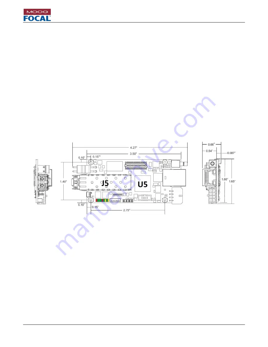
Stacking height for expansion cards is 16.00 mm to 17.22 mm. Nominal height should be minimum 16.15 mm
(0.636”) to take into account component tolerances. A 4.00 mm (minimum) standoff should be used under the 914-
HDE to ensure bottom side components have sufficient clearance.
Standard 5/32” standoffs are supplied with the
914-
HDE for mounting, along with 21/32” standoffs for expansion and media converter cards. Thermal gap material
should be used under the 914-HDE to further extract heat from the card.
Figure 10-1: 914-HDE Dimensions
When mounting, disassembling, or reassembling the 914-HDE (and stack), ensure that no fibers are subjected to
bends in excess of those held by the natural routing of the fibers. The minimum bend radius of the fibers should be
no less than 25 mm, though single partial bends may be less than this
– as low as 15 mm – without damaging the
fiber. Allowable long term values for bend radius are dependent on the fiber type and environment. Avoid even
temporary bends with a radius less than 15 mm, which may affect the long-term reliability of the fiber.
To ensure that the system maintains link and reliability through high shock and/or vibration environments, it is
recommended to secure the fiber LC connectors in the transceiver bushings using MIL-A-46146 equivalent RTV,
such as Dow Corning 3145 clear RTV. RTV may also be applied to power and data connectors, if required.


