background image

14 

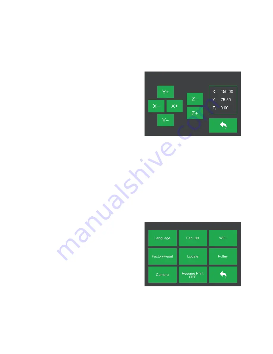
Manual Adjustment Screen 

The Manual Adjustment Screen displays the X and Y positions of the extruder and the Z 
position of the build plate. 


Touch the X+ button to move the 
extruder to the right. 


Touch the X- button to move the 
extruder to the left. 


Touch the Y+ button to move the 
extruder towards the back of the 
printer. 


Touch the Y- button to move the 
extruder towards the front of the printer. 


Touch the Z+ button to raise the build plate. 


Touch the Z- button to lower the build plate. 


Touch the Back button to return to the previous menu. 


Setting Menu 

The Setting Menu is displayed by touching the Setting button on the Tool Menu. 


Touch the Language button to select 
the language for the OSD Menu System. 


Touch the Fan button to turn the fan on 
or off. 


Touch the WIFI button to display the 
WIFI Screen. 


Touch the Factory Reset button to reset 
the printer's settings to their factory default values. 


Touch the Update button to update the printer's firmware. 


Touch the Pulley button to display the Pulley Type Selection Screen. 

Содержание 30526

Страница 1: ...MP Education Inventor 3D Printer P N 30526 User s Manual ...

Страница 2: ...in Unit 8 Extruder 9 OSD MENU SYSTEM 9 Top Menu 9 Print Menu 10 Print File Screen 10 Print Progress Screen 11 Print Tools Menu 11 Preheat Menu 12 Preheat Temperature Screen 12 Preheating Screen 13 Tool Menu 13 Manual Adjustment Screen 14 Setting Menu 14 Language Menu 15 WIFI Screen 15 Pulley Type Selection Screen 16 Status Screen 16 About Screen 16 ...

Страница 3: ...28 Initial Setup 29 Main Interface Overview 30 Loading a File 32 Generating a Model 32 Changing Views 35 Model Manipulation 36 Extruder 38 Supports 39 Printing a Model 41 File Menu 44 Edit Menu 45 Print Menu 46 View Menu 46 Tools Menu 47 Help Menu 49 CONNECTING THE PRINTER 49 USB Connection 49 Wi Fi Connection 50 UPDATING THE FIRMWARE 53 ...

Страница 4: ...HE CAMERA 57 Direct Login 57 Local Login 59 RESUME PRINTING 62 SPECIFICATIONS 63 TECHNICAL SUPPORT 64 REGULATORY COMPLIANCE 64 Notice for FCC 64 Notice for Industry Canada 65 EU Declaration of Conformity 65 WEEE Information 66 Safety Notice 67 ...

Страница 5: ...e reaching inside Ensure that the printer is turned off and unplugged from its power source before making repairs or performing service Do not install this device on an unstable surface where it could fall and cause either personal injury or damage to the device and or other equipment Do not subject the product to extreme force shock or fluctuations in temperature or humidity This device is intend...

Страница 6: ...ing hazard Never unplug the unit by pulling on the power cord Always grasp the connector head or adapter body CUSTOMER SERVICE The Monoprice Customer Service department is dedicated to ensuring that your ordering purchasing and delivery experience is second to none If you have any problem with your order please give us an opportunity to make it right You can contact a Monoprice Customer Service re...

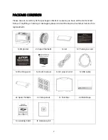
Страница 7: ...elow If anything is missing or damaged please contact Monoprice Customer Service for a replacement 1x 3D printer 2x Spool filament 1x Lid 1x Thank you card 1x Warning card 1x User s manual 1x AC power cord 1x USB cable 2x Spool holders 2x Side panels 1x Tool box 2x Build tape 1x Leveling Card 1x Accessory kit ...

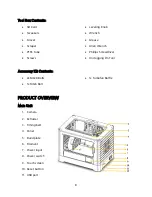
Страница 8: ...ease Allen Wrench Phillips Screwdriver Unclogging Pin Tool Accessory Kit Contents 2x M3x8 Bolts 1x M3x6 Bolt 1x Turbofan Baffle PRODUCT OVERVIEW Main Unit 1 Camera 2 Extruder 3 Timing belt 4 Panel 5 Build plate 6 Filament 7 Power input 8 Power switch 9 Touch screen 10 Reset button 11 USB port ...

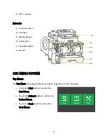
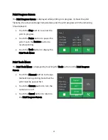
Страница 9: ...oling fan 17 Turbofan baffle 18 Nozzle OSD MENU SYSTEM Top Menu The Top Menu is displayed after the printer is powered on and initialized Touch the Print button to enter the Print Menu Touch the Preheat button to enter the Preheat Menu Touch the Tools button to enter the Tools Menu ...

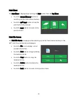
Страница 10: ...urn to the previous menu Print File Screen The Print File Screen is displayed after selecting a print file from internal memory or the SD card The print filename is displayed Touch the File icon to display a list of available model files Touch the Print button to begin printing the loaded print file Touch the Copy button to copy the loaded print file Touch the Delete button to delete the loaded pr...

Страница 11: ...s Touch the Pause button to pause the print Touch the Resume button to resume printing Touch the Tools button to display the Print Tools Menu Print Tools Menu The Print Tools Menu is displayed by touching the Tools button on the Print Progress Screen Touch the Filament button to change filament during printing Note that the print must be paused first Touch the Camera button to turn the camera on o...

Страница 12: ...the platform Touch the Start button to start preheating the extruder s and or platform Touch the Back button to return to the previous menu Preheat Temperature Screen The Preheat Temperature Screen is displayed by touching a Temperature button on the Preheat Menu Touch the arrows above and below the digits to increase or decrease that value Touch the Yes button to save the displayed temperature va...

Страница 13: ...ool Menu is displayed by touching the Tool button on the Top Menu Touch the Filament button to load or unload filament Touch the Level button to level the build plate Touch the Home button to move the extruder to the home position Touch the Manual button to display the Manual Adjustment Screen Touch the Setting button to display the Setting Menu Touch the Status button to display the Printer Statu...

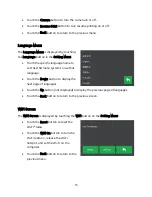
Страница 14: ...utton to raise the build plate Touch the Z button to lower the build plate Touch the Back button to return to the previous menu Setting Menu The Setting Menu is displayed by touching the Setting button on the Tool Menu Touch the Language button to select the language for the OSD Menu System Touch the Fan button to turn the fan on or off Touch the WIFI button to display the WIFI Screen Touch the Fa...

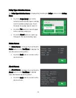
Страница 15: ...u system to use that language Touch the Down button to display the next page of languages Touch the Up button not displayed to display the previous page of languages Touch the Back button to return to the previous screen WIFI Screen The WIFI Screen is displayed by touching the WIFI button on the Setting Menu Touch the Reset button to reset the Wi Fi radio Touch the WIFI On button to turn the Wi Fi...

Страница 16: ...n to save changes to the selected pulley type Touch the Cancel button to abort any changes to the selected pulley type Status Screen The Status Screen is displayed by touching the Status button on the Tool Menu It displays the real time status of the printer Touch the Back button to return to the previous menu About Screen The About Screen is displayed by touching the About button on the Tool Menu...

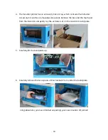
Страница 17: ...ontain the Inventor s lid Set this aside for now The Inventor printer and Power Cord are revealed 3 Lift the Inventor by its side openings and place it on a flat surface You can now see the Toolbox and USB Cable Inside the Toolbox you can find a Carving Knife a Scraper a package of Grease Tweezers and a Screw Box The Screw Box contains an SD Card some Screws a Leveling Knob and two PTFE Tubes ...

Страница 18: ...le side panels Remove the box and the foam pad from the Inventor and gently lay the extruder set on the Inventor s build plate 5 Carefully lift the build plate up 6 Carefully remove the two spools of PLA filament from under the build plate Congratulations you have finished unpacking your new Inventor 3D printer ...

Страница 19: ... install the filament It will only take about 5 10 minutes to setup the Inventor and prepare for your first 3D print 1 Lay the extruder set on top of the extruder seat with the two extruder fans facing the front 2 Secure the extruder set onto the extruder seat with two M3x12 screws from the bottom up 3 Use the M2 5 Allen wrench to unscrew the two turbofan bolts ...

Страница 20: ...turbofan sub assembly Place the turbofan sub assembly beside the turbofan seat Insert the bump on the turbofan seat to the turbofan sub assembly Screw in the two bolts Take an M3x6 bolt from the extruder s accessory kit and complete the installation 6 Lock the filament in place by securing it with the filament spool holder and turning it counterclockwise ...

Страница 21: ...fter installing the filament as shown in the image below 9 Ensure that the power switch is in the OFF position Locate the included power cord and plug it into the Inventor then plug the other end into a nearby AC power outlet Optionally locate the included USB cable plug one end into the Inventor then plug the other end into an available USB port on your computer ...

Страница 22: ...into your 3D printer 1 Remove the lid from the Inventor 2 If it is not already powered on flip the power switch to the ON position Wait for the system to stabilize then touch the Tool button on the Top Menu 3 Touch the Filament button then touch the Load Left button ...

Страница 23: ...ing it into the extruder at an upright angle Filament will start to extrude out of the nozzle Continue loading to ensure that the filament is extruding in a straight line Refer to the troubleshooting section if the filament is extruding abnormally Touch the Done button to finish loading Congratulations you have successfully loaded filament into your printer ...

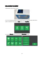
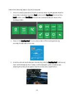
Страница 24: ... lid from the Inventor 2 If it is not already powered on flip the power switch to the ON position Wait for the system to stabilize then touch the Tool button on the Top Menu 3 Touch the Filament button then touch the Unload Left button ...

Страница 25: ... check whether the build plate is properly leveled or not A general rule of thumb is to leave a gap that is the thickness of a piece of paper However for printing finer objects 150 microns and lower use a feeler gauge to level the build plate as it requires a lesser gap between the nozzle and the build plate The Inventor uses a three point leveling system for the build plate At the bottom of the b...

Страница 26: ...ton on the Tool Menu The extruder and build plate will move to the starting position 2 Take out the Leveling Card You can view a video of the leveling process by scanning the QR code on the card 3 Once the extruder and build plate stop moving slide the Leveling Card continuously back and forth between the nozzles and the build plate while simultaneously adjusting the knob just enough so that the c...

Страница 27: ...ate the same amount of friction as the previous step 5 Touch the Next button again and repeat the same leveling steps 6 Touch the Next button The nozzle will move to the center of the build plate Slide the card through to make sure there is a slight friction Slowly adjust all screws by the same amount if there is no friction or too much friction ...

Страница 28: ... directly from the computer via a wired USB or wireless connection MP FlashPrint is available for Microsoft Windows and Linux in both 32 bit and 64 bit versions as well as Apple Mac OS X The MP FlashPrint installation packages can be found on the included SD card Once you have located the software installation package run the application and follow the onscreen installation instructions ...

Страница 29: ... the program If this is the first time the program has been run you will be presented with a dialog asking you to select the Machine Type Choose the MP Inventor entry You can also select the Machine Type from within the program by clicking Print Machine Type MP Inventor as shown in the screenshot below ...

Страница 30: ...e The icons have the functions listed in the table below Icon Function Load Loads a model or Gcode file FlashPrint supports STL OBJ and FPP model files You can also load a PNG JPG JPEG or BMP file and FlashPrint will generate a model from the image See the Generating a Model section for details Supports Enters the Support Edit mode ...

Страница 31: ...to the SD card View Views the FlashPrint home screen from one of six viewing angles Move Moves the model around on the X Y plane Hold the SHIFT key then click to move the mode along the Z axis Rotate Turns and rotates the model Scale Scales the size of the model Cut Cuts the model into several parts ...

Страница 32: ...ile from the list of recently used files Drag and drop the file onto the FlashPrint icon on the desktop to launch FlashPrint and load the file Generating a Model FlashPrint can generate a 3D model file from a PNG JPG JPEG or BMP image file When you load the image file the following dialog box will be displayed which allows you to set several model parameters Shape Determines the basic shape of the...

Страница 33: ...of the model Bottom Thickness Sets the thickness of the bottom of tube canister and lamp type models Top Diameter Sets the diameter for the top of tube canister and lamp type models Bottom Diameter Sets the diameter for the bottom of tube canister and lamp type models The following screenshots illustrate the five basic shapes Plane Tube ...

Страница 34: ...34 Canister Lamp Seal ...

Страница 35: ...preset camera angles using one of the following methods Click the View menu then select one of the six options from the drop down list Click the View icon then click it again and a submenu will appear with six options for selection Reset View You can reset the camera angle to the default using one of the following methods Click the View menu then select Home View Click the View button the click it...

Страница 36: ...n Platform to ensure that the model is in the build area and in contact with the build platform Rotate Click on the model to select it You can them rotate the model in all three planes in a variety of ways Click the Rotate icon and three mutually perpendicular rings will appear around the model Click and hold on one ring and move the mouse to rotate the model in that plane Click the Rotate icon th...

Страница 37: ...ill scale the model in proportion when changing any size value Cut Click the model to select it then double click the Cut icon to set the cut plane in a variety of ways Left click and drag the cursor across the model to set the cut angle Select the X Plane option to cut the model vertically Select the Y Plane option to cut the model vertically ...

Страница 38: ...38 Select the Z Plane option to cut the model horizontally Extruder Double click the Extruder icon to select the left and or right extruder for printing ...

Страница 39: ...on Click the Back button when finished editing the supports Support Options Click the Support Options button to display the Support Options dialog You can select Treelike or Linear supports Treelike supports are built at angles while Linear supports are linear vertical supports for the overhanging elements When you click the OK button the software will generate the appropriate support structures I...

Страница 40: ...ding down the mouse button drag the mouse to the termination point The supports preview will be displayed with the support highlighted If the support surface doesn t need support or the support column angle is too large the support will not be generated Clear Supports Click the Clear Supports button to remove all existing supports If you change your mind click the Undo option or press CTRL Z Delet...

Страница 41: ...use Supports Enable or disable the creation of supports Raft Enables or disable a Raft which is several layers of material on the build plate to help with model adhesion Wall Check the Wall box to help clear leaking filament from a second extruder during dual color printing Brim Check the Brim box to print a ring of filament around the model to help prevent warping and assist with bed adhesion Res...

Страница 42: ...the top of the model The maximum value is 30 and the minimum is 1 Bottom Solid Layers Sets the number of solid layers at the bottom of the model The maximum value is 30 and the minimum is 1 Infill Click the Infill tab to reveal the infill options Infill is the structure that is printed inside the model Infill directly affects the strength of the printed mode Fill Density Sets the fill density in 5...

Страница 43: ...d models For PLA printing 100mm sec is recommended Temperature Click the Temperature tab to reveal the temperature options Right Extruder Sets the operating temperature of the extruder from 0 to 248 C in 5 C increments Set the temperature according to the type of filament being printed Platform Sets the operating temperature of the build platform from 0 to 120 C in 5 increments Set the temperature...

Страница 44: ...ave As Click File Save As to save the project or model file Examples Click File Examples to load one of four built in sample models Recent Files Click File Recent Files to choose from a list of recently loaded files Preferences Click File Preferences to set several General and Print preferences Language Allows you to select the language used in FlashPrint Font Size Allows you to set the size of th...

Страница 45: ... Edit Empty Undo Stack to clear the software s memory of recent undos This has the same effect as saving and reloading the project or model file Select All Click Edit Select All or press CTRL A to select all models in the scene Duplicate Click Edit Duplicate or press CTRL V to copy the selected model s Delete Click Edit Delete or press the Del key to delete the selected model s Auto Layout All Cli...

Страница 46: ...rinter to use with FlashPrint This printer is the MP Inventor View Menu The View Menu contains the following options Home View Sets the camera to the default position Top View Sets the camera to look directly down onto the build area Bottom View Sets the camera to look directly up towards the build area Left View Sets the camera to look at the build area from the left Right View Sets the camera to...

Страница 47: ...ch mouse click Six Blue Arrow Buttons The buttons allow you to manually move the extruder and build plate The amount they will move with each click of the mouse is determined by the Jog Mode settings Stop Click the Stop button to abort any current movement XYZ Coordinates Displays the current position of the extruder and build plate You cannot edit the displayed values Make Current Position Zero C...

Страница 48: ... unlock the stepper motor so the extruder and build plate can be manually moved LED Color Allows you to set the LED color of the Inventor printer Motor Speed RPM Controls the speed of the filament feed wheel Extruder Duration Controls the motor rotation time Forward Feeds filament to the extruder Reverse Unloads filament from the extruder Stop Stops motor movement when feeding or unloading filamen...

Страница 49: ...onnection or a wireless Wi Fi connection in AP mode or STA Station mode USB Connection Perform the following steps to connect your PC to the Inventor printer using a wired USB connection 1 Plug one end of the included USB cable into the USB port on the printer then plug the other end into an available USB port on your computer 2 Power on the printer and your computer then start the FlashPrint soft...

Страница 50: ...lick Connect 4 Open your internet browser Type 10 10 100 254 and press the Enter key on your keyboard Enter the username and password to login The default username and password are both admin The control panel will appear after successful login 5 Click the WiFi Set tab on the left then set the WiFi Work Mode to AP mode or STA mode then click Restart to make the changes take effect AP mode configur...

Страница 51: ...l If you choose to use AP mode you can set the network name Inventor1 and password of the hotspot If you don t want to use a password enter NONE Click the Save button and restart it Connect your PC to the network named Inventor1 or the name you set Open FlashPrint then click Print Connect Machine Select Wi Fi as the Connect Mode and enter the IP Address as shown on the Inventor s screen Click Conn...

Страница 52: ...ut the SSID and password of your existing Wi Fi connection If your Wi Fi connection does not use a password enter NONE into the password field Then click the Save button and restart it Restart the Inventor printer then open the WIFI Screen ...

Страница 53: ...etects and downloads the up to date firmware If an update is available a dialog box will appear to remind you of the update Perform the following steps to update the firmware 1 Click Tools Update firmware You must sever any existing connection with the printer before updating If a connection exists it will prompt you to cut the connection Click the Yes button to cut the connection 2 Choose the cor...

Страница 54: ...ion and dual extrusion With single extrusion printing you can choose which print head to use for making the print Dual extrusion printing is useful if you want to print with two color or print complex models that require supporting material Perform the following steps to print a model on the Inventor printer from a Gcode file saved to the SD card Generating Gcode 1 Plug the included SD card into a...

Страница 55: ...d Center buttons to ensure the model is in contact with the center of the build platform 6 Click the Print icon then change the settings as appropriate for your filament type and model Preview Check the Preview box if you want to preview the model after slicing is done Print When Slice Done Because we are printing from the SD card uncheck this box to save the Gcode file to the SD card Machine Type...

Страница 56: ... recommended to leave them at the default values 7 Click OK to save the Gcode file to the SD card You can rename the file as desired and save it as either a g or gx file Files with a gx extension can be previewed while g files cannot 8 Eject the SD card then plug it into the SD card slot on the printer 9 Power on the Inventor printer 10 Ensure that the build plate is leveled and that filament is l...

Страница 57: ... print USING THE CAMERA The Inventor printer includes a camera which allows you to monitor the print on your phone Download and install the XMEye app from the App store After installing the app perform one of the following connection methods to use the camera Direct Login 1 If the printer is not already powered on flip the power switch to the ON position Wait for the printer to stabilize then touc...

Страница 58: ...will have different combinations of letters and numbers for the rest of the name If the hotspot does not appear in the list touch the Reset button on the Camera Screen Select the xmjp entry then enter the password 1234567890 4 Open the XMEye app after your phone has successfully connected with the camera s Wi Fi signal 5 Tap Direct Login to review the video The camera is now directly connected to ...

Страница 59: ... Tool button on the Top Menu then touch the Setting button 2 Touch the Camera button then touch the On button to turn the camera on You will see the words Turned on in the upper left corner of the screen 3 Connect your mobile phone to an available Wi Fi hotspot then open the XMEye app Tap Local Login then tap the in the upper right to add a device ...

Страница 60: ...Check the Ensure the indicator and Device operation options then tap Complete all the above operation 5 Touch the Reset button on the printer s screen then tap Yes in the dialog that appears on your phone Note that the Android version of the app does not display this dialog ...

Страница 61: ...start over from the beginning Tap the green point on your phone 7 You can now see the camera in the device list Tap it to watch the video 8 After adding the device the camera Wi Fi hotspot signal xmjp beye xxxx will disappear You are now connected to the internet and can review the video from anywhere you have internet access ...

Страница 62: ...e printer is not already powered on flip the power switch to the ON position Wait for the printer to stabilize touch the Tool button on the Top Menu then touch the Setting button 2 Touch the Resume Print button to enable print resuming 3 If the printer loses power during a print the following dialog will appear after power is reapplied Touch the Yes button to resume printing ...

Страница 63: ...0 0025mm Filament Diameter 1 75mm 0 07mm Filament Types ABS PLA Conductive PLA Flexible Filament Nozzle Diameter 0 4mm Build Speed 10 200 mm sec Software FlashPrint Supported Input Formats 3MF STL OBJ FPP BMP PNG JPG JPEG Supported Output Formats G GX Supported Operating Systems Windows XP and later 32 bit and 64 bit Mac OS X Linux Input Power 100 240 VAC 50 60 Hz 4 5A 2 5A Connectivity USB cable ...

Страница 64: ...rference 2 This device must accept any interference received including interference that may cause undesired operation Warning Changes or modifications not expressly approved by the party responsible for compliance could void the user s authority to operate the equipment This equipment has been tested and found to comply with the limits for a Class B digital device pursuant to Part 15 of the FCC R...

Страница 65: ...Cet appareil numerique de la classe B est conforme a la norme NMB 003 du Canad EU Declaration of Conformity Monoprice Inc declares the product described within this user guide or manual is in compliance with below applicable directives The full text of the EU Declaration of Conformity is available at the following internet address https www monoprice com product c_id 107 cp_id 10724 cs_id 1072403 ...

Страница 66: ...is symbol and or its packaging must not be disposed of with unsorted municipal waste The symbol indicates that this product should be disposed of separately from regular household waste streams It is your responsibility to dispose of this and other electrical and electronics products via designated collection facilities appointed by the government or local authorities Correct disposal and recyclin...

Страница 67: ...ower outlet must be located nearby the equipment and its access must be easy WARNING Use this product in a well ventilated area Wi Fi is a registered trademark of Wi Fi Alliance Microsoft and Windows are either registered trademarks or trademarks of Microsoft Corporation in the United States and or other countries Apple Mac and OS X are trademarks of Apple Inc registered in the U S and other count...

Отзывы: