background image

SR5i Technical Manual

                      TSP095.doc                                          Issue 1.0 – July 2004

©

Money Controls 2004.  All rights reserved.

2.  Introduction 

The SR5i coin acceptor has been designed to be compatible with the standard 5” format
currently used throughout the vending, amusement and leisure industries.  

Through the development of Series Resonance technology, and now the incorporation of
AccepTelligence

TM

 an intelligent expert system, the SR5i offers increased levels of acceptance

and security. Each acceptor will accept up to 16 different coins or 15 coins plus one token.

Depending on your requirements, the SR5 series can be set-up to be backwards compatible
with the C220B, C420, C435, and C435 UK AWP.  This will be determined by the 

Mode.

Mode   1 = C435
Mode   2 = C435 - BACTA Binary

As with all new Money Controls products other enhancements have been made to the SR5i
series as well as the new sensing technology.

These include:-

¾


ccTalk

  serial communication.

 (see sections 

19

 to 

22

)

¾


Extended 

Teach and Run™

 options.

¾


Coinless programming.

¾


Improved sorter coin detection.

Содержание SR5i

Страница 1: ...hin this document Money Controls Ltd shall not incur any penalties arising out of the adherence to interpretation of or reliance on this standard Money Controls Ltd will provide full support for this...

Страница 2: ...sorting 25 14 Active Manifold Interface 27 15 RS232 Interface 28 15 1 Recommended PC connection wiring details 28 15 2 Signal descriptions 28 16 Flash Programming Interface 29 16 1 Details of PCB con...

Страница 3: ...nity 48 25 33 Shock Vibration Immunity 48 25 4 Environmental specification 48 25 5 Material Flammability Rating 48 25 6 Top Entry dimensions 49 25 7 Bezel Dimensions 50 25 8 Front Entry Dimensions 51...

Страница 4: ...tive Manifold connector 27 Figure 13 D Type Recommended Connections 28 Figure 14 Bank Select switches 30 Figure 15 Rotary switch 31 Figure 16 SR5i Label Details 36 Figure 17 ccTalk pin header 37 Figur...

Страница 5: ...SR5i Technical Manual TSP095 doc Issue 1 0 July 2004 Money Controls 2004 All rights reserved 1 Diary of changes Issue 1 0 April 2004 1st issue based on functional spec V9 0...

Страница 6: ...fers increased levels of acceptance and security Each acceptor will accept up to 16 different coins or 15 coins plus one token Depending on your requirements the SR5 series can be set up to be backwar...

Страница 7: ...ristics measured from the inserted coin match the stored window readings in all respects then the coin is recognised as being true The accept gate will then open and the coin will pass through the acc...

Страница 8: ...dustry Standard Shown below is the typical UK AWP Standard configuration and dimensions The SR5i is covered in more detail in section 10 2 Basically this would consist of a Top Entry SR5i Manifold 6 U...

Страница 9: ...ion 9 2 Parallel Interface See section 10 3 Sorter Override See section 12 4 Routing Plug See section 13 5 Serial interface ccTalk See section 20 6 Active Manifold See section 14 7 Flash Programming S...

Страница 10: ...e stud positions shown below are factory fitted at MCL A represents Money Controls back channel compatible B represents Industry Standard back channel compatible C is a customer specific requested opt...

Страница 11: ...above Ripple voltage 120Hz 1 Volt Ripple voltage 120Hz 100mV Ripple voltage 1KHz 20mV Table 3 Current Consumption Typical 70mA Maximum 2 0A with sorter 3 0A with sorter and active manifold 7 1 Accept...

Страница 12: ...ll the following inputs have the same electronic configuration Inhibits Bank Select Overrides Select The hardware configuration for these inputs is shown below Figure 4 Input Hardware Configuration Ta...

Страница 13: ...page 32 Alarm and Rundown settings D 8 1 Power up Diagnostics When the SR5i powers up it performs an EEPROM self check If there is a problem with the checksum the LED will turn red and no coins will...

Страница 14: ...indicating whether a coin or a token has been entered Normally when there is no coin or token in the entry both the opto detectors are active as they are receiving infrared light from the correspondi...

Страница 15: ...Inhibit 5 Input 17 Inhibit 6 Input 18 Inhibit 7 Input 19 Inhibit 8 Input 20 Bank Select 1 Input 21 Bank Select 2 Input Note Inhibits are mapped directly from Bank 1 to Bank 2 Output Codes The Select L...

Страница 16: ...0V 13 Inhibit 3 20p Inhibit 3 20p 14 Inhibit 2 50pN 50pO Inhibit Linked to 5p 10p 50pN 50pO 15 Inhibit 1 1 Inhibit 1 1 16 Inhibit 5 Tkn Inhibit 5 Tkn 17 Inhibit 6 5p Inhibit 6 2 Note Inhibits are mapp...

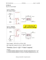
Страница 17: ...e specification then the performance of the Accept outputs is not guaranteed On acceptance of a true coin the transistors COM A dependant are turned on for a period of 80ms 2 5 to within 1 volt of COM...

Страница 18: ...SR5i Technical Manual TSP095 doc Issue 1 0 July 2004 Money Controls 2004 All rights reserved Continued Figure 6 Accept Outputs...

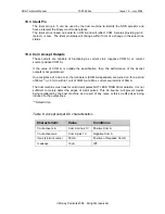
Страница 19: ...de outputs 10 6 Inhibit Lines The Inhibit inputs define whether a programmed coin will be accepted or not Which coins are affected by the inhibit inputs is decided in conjunction with the Bank Select...

Страница 20: ...L switch will have no effect When a Bank Select input is Low3 then the corresponding bank of coins are de selected i e inhibited When a Bank Select input is High4 then the corresponding bank of coins...

Страница 21: ...ompatibility 1 Inhibit 5 controls windows 5 6 Inhibit 6 controls windows 7 8 C200 series C420 SR5 Modes 3 10 11 2 Inhibit 5 controls windows 5 7 Inhibit 6 controls windows 6 8 C335 3 Standard Inhibit...

Страница 22: ...be achieved either using the routing plug see Sorting Modes page 25 or having the paths pre programmed into EEPROM Switching between EEPROM and routing plug can be achieved using the rotary switch se...

Страница 23: ...M Overrides 1 to 4 control paths A D as shown irrespective of method used Taking the relevant input Low indicates to the acceptor that the route is overridden The coin will then travel down the next p...

Страница 24: ...r to use 8 way sorting the paths MUST be programmed in EEPROM Of the 8 possible routes for an accepted coin only routes 1 to 7 have a sorter override input Taking the relevant input Low indicates to t...

Страница 25: ...mum of 4 paths the relevant default path e g 4 way could be coin 2 to path C then D B default A See Figure 7 In this example both coins 1 and 2 are diverted to path D Any number of coins can be connec...

Страница 26: ...SR5i Technical Manual TSP095 doc Issue 1 0 July 2004 Money Controls 2004 All rights reserved e g 8 way could be coin 6 to path 1 then 4 3 7 default 8 See Figure 8...

Страница 27: ...y 2004 Money Controls 2004 All rights reserved 14 Active Manifold Interface Figure 12 Active Manifold connector This two pin connector is switched to operate the divertor flap within the active manifo...

Страница 28: ...DSR Data set Ready I 7 RTS Request To Send O 8 CTS Clear To Send O 9 RI Ring Indicator Not used 15 1 Recommended PC connection wiring details Figure 13 D Type Recommended Connections 15 2 Signal desc...

Страница 29: ...input link to pin 4 I 7 Key No connection Used for polarising key No connection 8 BUSY Busy output no connection required O 9 CE Chip Enable active Low I 10 HOLD EPM Hold EPM active Low I 16 3 Plug w...

Страница 30: ...t of taking the relevant Bank Select input on the main parallel connector Low If either the switch is closed or the Bank select input is Low then the bank is de selected inhibited The Bank Select swit...

Страница 31: ...amming Mode 0 Token disabled x x 1 5 Select token 1 to 5 x x 6 Routing Replication x x 7 Power up diagnostics Up Enable diagnostics Dn Disable diagnostics x 8 Debugging Up Pulse solenoids Dn No action...

Страница 32: ...ion 8 allows the solenoid test sequence to be enabled pulsed solenoid duty cycle is 500ms on 500ms off If the sorter is enabled on the SR5i then the software cycles through a solenoid test sequence Ac...

Страница 33: ...nd Rundown settings D For Alarm details see section 8 Alarms To set these options to those required ensure that the SR5i is powered up through the main parallel connector Changes cannot be made in ser...

Страница 34: ...d switch positions are selected press and hold the program button situated underneath the rotary switch the LED will change from Green to Yellow release the program button the LED will change back to...

Страница 35: ...l stop flashing The SR5i automatically selects the newly programmed token after Teach and Run Turn the rotary switch to position C to accept the newly programmed token press the program button the LED...

Страница 36: ...SR5i Technical Manual TSP095 doc Issue 1 0 July 2004 Money Controls 2004 All rights reserved 19 Label Details Figure 16 SR5i Label Details...

Страница 37: ...tion please refer to the current ccTalk generic standard Connector type 10 Way DIL connector 5 on Figure 2 Pin 1 DATA Pin 2 0V Not used Pin 3 Not used Pin 4 0V Not used Pin 5 RESET Pin 6 Not used Pin...

Страница 38: ...t output lines 188 Request default sorter path 237 Read input lines 185 Modify coin id 236 Read opto states 184 Request coin id 233 Latch output lines 183 Upload window data 232 Perform self test 182...

Страница 39: ...s 23 Credit sensor reached too early 24 Reject coin repeated sequential trip 25 Reject slug 35 Number of coin meter pulses overloaded 36 Games overloaded 254 Coin return mechanism activated flight dec...

Страница 40: ...dard Interface This circuit uses an open collector transistor to drive the data line and a diode protected straight through receiver Figure 18 Circuit 1 ccTalk Standard Interface Typical Components Di...

Страница 41: ...ace Assuming that the transmitting device is capable of sinking a reasonable amount of current a direct diode interface can be used rather than a full transistor interface Although cheaper to implemen...

Страница 42: ...2 3 Circuit 3 ccTalk Direct Interface A very low cost solution is to interface a single pin on a microcontroller directly onto the ccTalk data line The pin can be switched between active low for trans...

Страница 43: ...4 ccTalk PC Interface The circuit below shows how to connect the 9 pin serial port of a PC to the ccTalk data bus The only integrated circuit required is a Maxim level shifter which operates off a sin...

Страница 44: ...dy can be withdrawn away from the frontplate 3 When re assembling line up the keyhole slots in the body with the retainers on the frontplate Push the body forward and downwards When in position catch...

Страница 45: ...st undo screw 9 and remove the rundown cover Carefully slide the gate spring 12 towards the rear of the SR5i and remove Pull the gate forward and downward to remove Re fitting is the reverse of remova...

Страница 46: ...ower and re apply LED should be green Power supply Voltage less than 10V NB voltage drops when solenoid s are activated Accept gate Gate not free or dislocated Connector Loose Coin rundown Dirty Poor...

Страница 47: ...2 degrees of the vertical in any plane It is intended for use in stationary environments 25 2 Coin Token Sizes The accepted range of coin sizes are shown below This Graph is only intended as a guide I...

Страница 48: ...ompliant with BS 2011 part 2 1 IEC 68 2 27 25 4 Environmental specification Table 16 Environmental Ranges Operating temperature range 0 C to 55 C 10 to 75 RH non condensing Storage temperature range 2...

Страница 49: ...SR5i Technical Manual TSP095 doc Issue 1 0 July 2004 Money Controls 2004 All rights reserved 25 6 Top Entry dimensions Figure 24 SR5i Top Entry with Sorter Dimensions...

Страница 50: ...SR5i Technical Manual TSP095 doc Issue 1 0 July 2004 Money Controls 2004 All rights reserved 25 7 Bezel Dimensions Figure 25 Oval Bezel Dimensions Figure 26 Panel Fixing Dimensions...

Страница 51: ...SR5i Technical Manual TSP095 doc Issue 1 0 July 2004 Money Controls 2004 All rights reserved 25 8 Front Entry Dimensions Figure 27 SR5i Front Entry Dimensions...

Страница 52: ...erved 25 9 Manifold Coin Exit Paths Figure 28 SR5i Manifold Coin Exit Paths Note C235 C255 C335 and SR5 Mode 5 have the same sorter paths Red Black C435 and all the other SR5 s fitted with a sorter ar...

Страница 53: ...head screw 3 Front entry gate piece with ball stabiliser 4 Gate snubber 5 4 2 x 3 8 pozi csk screw 6 Quick release latch spring Front Entry 7 Front Entry piece 8 M4 0 full nut 9 4 2 x 5 16 pozi pan h...

Страница 54: ...o assist the reader in the use of this product and therefore Money Controls shall not be liable for any loss or damage whatsoever arising form the use of any information or particulars in or any incor...

Отзывы: