SR5i Technical Manual
TSP095.doc Issue 1.0 – July 2004
©
Money Controls 2004. All rights reserved.
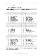
15. RS232 Interface
¾
Cost option
¾
Industry standard 9 way D-type vertical pcb mounting socket (Female)
Table 8: RS232 Signal Connections
PIN
SIGNAL
NAME
FUNCTION
Input (I) /
Output(O) /
Power(P)
1
DCD
Received line signal detector
(Data Carrier Detect)
I
2
Rx Serial
RS232 received data input
I
3
Tx Serial
RS232 transmit data output
O
4
DTR
Data Terminal Ready
O
5
Gnd
Signal ground
P
6
DSR
Data set Ready
I
7
RTS
Request To Send
O
8
CTS
Clear To Send
O
9
RI
Ring Indicator
Not used
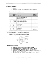
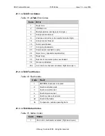
15.1 Recommended PC connection wiring details:
Figure 13: ‘D’ Type Recommended Connections
15.2 Signal descriptions
¾
Data is transmitted and received on pins 3 and 2 respectively.
¾
Data set ready
(DSR)
is an indication from the PC Host that it is active.
¾
Data Terminal Ready
(DTR)
indicates to the PC Host that it is active.
¾
Data Carrier Detect
(DCD)
indicates that carrier for the transmit data is active.
¾
Request to Send
(RTS)
and Clear to Send (
CTS)
signals are constantly on
throughout the communication session.
¾
The Ring Indicator
(RI)
signal is only used for synchronous communication.


