Quality Crimp Handbook
Order No 63800-0029
Release Date:09-04-03
UNCONTROLLED COPY
Page 10 of 24
Revision: B
Revision Date: 10-07-05
SECTION 6
PROCEDURES
Tool Setup
(Reference Procedures Flow Chart)
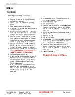
1. Check that tooling is clean and not worn. If necessary,
clean and replace worn tooling.
2. Disconnect power to the press and remove guarding
devices.
3. Install the appropriate tooling into the press.
4. Load terminals into the tooling so that the first terminal is
located over the anvil.
5. Manually cycle the press to help ensure a complete cycle
can be made without interference. If it cannot, remove
tooling and check press shut height. Go to procedure 3.
6. Check that the tooling is aligned. Check the impression
on the bottom of the crimp that was made by the anvil
tooling. Check that the extrusions and crimp form are
centered. If not, align tooling and go to procedure 5.
7. Check that the terminal feed locates the next terminal
over the center of the anvil tooling. If not, adjust
terminal feed and feed finger and go to procedure 5.
8. Re-install all safety devices that were removed during the
set-up.
(Follow all safety requirements listed in
individual press and/or tooling manuals.)
9. Crimp sample terminals under power.
10. Evaluate cut-off tab length and conductor bell mouth. If
adjustment is necessary, disconnect power to the press
and remove guarding. Adjust track position. Manually
cycle the press and check the feed finger for feed
location, go to procedure 7.
11. Evaluate conductor brush. If adjustment is necessary,
disconnect power to the press and remove guarding.
Adjust wire stop for bench applications or press position
on automatic wire processing equipment. Go to
procedure 8.
12. Evaluate insulation position. If necessary, adjust strip length,
crimp new samples, and go to procedure 11.
13. Loosen insulation crimp height.
14. Crimp sample terminals.
15. Measure conductor crimp height and compare to specification.
If necessary, disconnect power and remove guarding. Adjust
conductor crimp height, install guards, connect power, and go
to procedure 14.
16. Perform a pull force test. Refer to troubleshooting (Section 9)
if this test fails.
17. Adjust insulation crimp.
18. Crimp sample terminals.
19. Evaluate insulation crimp. If necessary, disconnect power and
remove guarding. Adjust insulation crimp height, install
guards, connect power, and go to procedure 18.
20. Measure crimp height and compare to specification. If
necessary, disconnect power and remove guarding. Adjust
conductor crimp height, install guards, connect power, and go
to procedure 18.
21. Document measurements.
Please Work Safely At All Times.

