background image

5014166 D

September 2015

ImageXpress

®

 Micro

High Content Imaging System

Options

User Guide

ImageXpressOptionsUserGuide.book  Page 1  Wednesday, September 9, 2015  3:54 PM

Содержание ImageXpress Micro

Страница 1: ...5014166 D September 2015 ImageXpress Micro High Content Imaging System Options User Guide ImageXpressOptionsUserGuide book Page 1 Wednesday September 9 2015 3 54 PM...

Страница 2: ...ir product names as trademarks Each product is shipped with documentation stating specifications and other technical information Molecular Devices products are warranted to meet the stated specificati...

Страница 3: ...Dioxide 14 Loading the Sample Plate 15 Environment Control Software 18 Environmental Parameters in Image Information 19 Performing Timelapse Experiments 20 Reviewing Timelapse Data 23 Chapter 2 Fluid...

Страница 4: ...45 Cleaning the Water Reservoir 46 Waste Disposal Box and Plate Sealing Ring 47 Chapter 4 Transmitted Light Option Operations 49 Transmitted Light Hardware 50 Transmitted Light Software Configuration...

Страница 5: ...ent Imaging System Conventions In this user guide the following typographical conventions are used CAUTION Indicates an operation that can cause damage to the instrument device or data if the precauti...

Страница 6: ...ftware are available in this reorganized menu structure The procedures in this guide describe both the default menu structure and the simplified menu structure You can use the Menu Map in the Help men...

Страница 7: ...0 In Europe call 44 0 118 944 8000 Part of effective communication with Molecular Devices is determining the channels of support for the ImageXpress Micro System including the MetaXpress Software Mole...

Страница 8: ...hen you call To find your system ID number in the MetaXpress Software click Help About MetaXpress The About dialog displays your system ID number The system serial number is located on your instrument...

Страница 9: ...se imaging capabilities the environmental enclosure can accommodate a single channel fluidics robot for delivering compounds during experimentation The ImageXpress Environment Control option can be in...

Страница 10: ...een 15 PSI and 20 PSI The Environmental Control Option Controller or the Systems Power Options Controller controls the flow to the space above the plate maintained by the live cell sealing ring If a p...

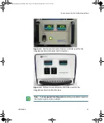
Страница 11: ...ImageXpress Micro Standard and XLS Systems Figure 1 2 Systems Power Options Controller used for the ImageXpress Micro Confocal System Note The Compound Plate Temperature setting is available only when...

Страница 12: ...tion warm air hose and carbon dioxide tubing on the back of the Environmental Control Option Controller Figure 1 4 Environment Control option warm air hose and carbon dioxide tubing on the back of the...

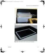
Страница 13: ...ption Operations 5014166 D 13 Figure 1 5 Environment Control option water reservoir Figure 1 6 Environment Control option live cell sealing ring ImageXpressOptionsUserGuide book Page 13 Wednesday Sept...

Страница 14: ...ght Most 96 well and 384 well plates are standard height The standard height for these plates is 14 35 mm 0 25 mm 0 5650 inches 0 0098 inches Deionized water to maintain humidity Setting Up Environmen...

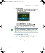
Страница 15: ...d After you release the current temperature in the chamber is displayed Setting Up the Water Reservoir Air supplied to the environmental enclosure flows through the water reservoir to make sure the ai...

Страница 16: ...deionized water into the luer lock 5 View the water reservoir through the open top panel Figure 1 8 Environment Control option water reservoir 6 Dispense the deionized water from the syringe into the...

Страница 17: ...ly 15 PSI to 20 PSI 5 From the top of the ImageXpress Micro System lift the insert surrounding the top door and remove it Keep the top door of the instrument closed 6 Verify that there is a steady flo...

Страница 18: ...ick Screening Plate acquisition and Control Eject Plate to open the top door of the instrument 2 Insert the sample plate into the stage and then remove the lid from the plate If there are concerns abo...

Страница 19: ...ealing ring 4 In the MetaXpress software click Screening Plate acquisition and Control Load Plate to close the top door of the instrument Note Temperature fluctuations in the plate and its surrounding...

Страница 20: ...zed water or media into these areas This helps to increase the thermal mass of the plate and reduces overall evaporation 1 Note Due to the changes in Z height over time you might need to adjust the pl...

Страница 21: ...s Low or OK Figure 1 10 Environment Control dialog When the top door of the ImageXpress instrument is opened the MetaXpress Software triggers the environment control to increase the flow rate of the c...

Страница 22: ...s environmental information when images are captured as shown in Figure 1 11 on page 22 Figure 1 11 Image information annotation with environmental parameters Note There are wire sensors in the system...

Страница 23: ...reening Plate Acquisition Setup 2 In the Plate Acquisition Setup dialog in the Configure tab open the Acquisition tab See Figure 1 12 Figure 1 12 Acquire Time Series 3 Select Acquire Time Series Note...

Страница 24: ...t one of the following methods for acquiring a series of timelapse images corresponding to different types of experiments All selected wells is used for long timelapse experiments The system images al...

Страница 25: ...options include First timepoint only Recommended for fast kinetic experiments All timepoints Recommended for long timelapse experiments Every Nth timepoint Offers the flexibility to autofocus regularl...

Страница 26: ...r this wavelength At start of experiment Only the first time point is acquired for this wavelength At start end of experiment Only the first and last time points are acquired for this wavelength Every...

Страница 27: ...g Review Plate Data Figure 1 16 Review Plate Data dialog 2 Click Select Plate 3 In the Select Plate for Review dialog select a plate and then click Select 4 In the Data view list click Time vs Well Th...

Страница 28: ...the image pane Note To clear the selection click Clear Selection at the bottom of the dialog Note In a timelapse experiment the time starts when the first well is acquired If the acquisition time exc...

Страница 29: ...press Software desktop 3 In the MetaXpress software click Stack Make Movie In the Simplified Menu Structure click Edit Stack Make Movie Figure 1 18 Make Movie dialog 4 In the Make Movie dialog select...

Страница 30: ...ImageXpress Micro High Content Imaging System Options User Guide 30 5014166D ImageXpressOptionsUserGuide book Page 30 Wednesday September 9 2015 3 54 PM...

Страница 31: ...e following sections Fluidics Hardware on page 31 Setting Up Fluidics Hardware on page 33 Configuring Fluidics Software Stations and Properties on page 35 Doing Fluidics Experiments on page 43 Prevent...

Страница 32: ...ip stripper Used for ejecting tips Waste bin Used to contain ejected tips and discarded liquid Doors with safety interlocks Prevents doors from being opened during operation Figure 2 1 Fluidics hardwa...

Страница 33: ...U bottom and V bottom plates are beneficial when withdrawing and dispensing very small volumes of compound Setting Up Fluidics Hardware The FSE Field Service Engineer installs the ImageXpress Fluidics...

Страница 34: ...taXpress and then right click Meta Imaging Series Administrator and select Run as administrator to start the MetaXpress Meta Imaging Series Administrator software 2 Click Configure Hardware 3 In the C...

Страница 35: ...ss the functions from the menu To configure fluidics software 1 In the MetaXpress Software click Screening Plate Acquisition Setup Figure 2 3 Plate Acquisition Setup dialog Note The Configure Fluidic...

Страница 36: ...e Configure tab open the Acquisition tab Figure 2 4 Plate Acquisition Setup dialog Configure tab Acquisition tab 3 Under Acquisition select Use Fluidics 4 Open the Fluidics tab Figure 2 5 Plate Acquis...

Страница 37: ...uidics Stations dialog for each Tip Tray select a Tip Type 7 For each Compound Plate select a Plate Type Note The system comes pre configured with settings for FLIPR Tetra 96 and 384 tips Note You can...

Страница 38: ...o one of the following If you selected Track Volume then select Track Liquid Surface and then go to Step 11 Optionally select Track Volume select Track Liquid Surface clear Track Volume and then go to...

Страница 39: ...ispense operations at the imaging location When enabled if Track Liquid Surface is also selected then dispensing occurs near the liquid surface otherwise the dispensing occurs near the bottom of the w...

Страница 40: ...the following procedure to control the fluidics station manually CAUTION Improper tip definitions can cause the pipette tip to crash into the sample plate Molecular Devices recommends that you do not...

Страница 41: ...lly pick up and eject tips draw and dispense fluid and mix For example to remove 20 l from well A01 in the compound plate and add it to the sample plate specify the following Action Draw Station Compo...

Страница 42: ...steps that you want to record See To control fluidics manually on page 41 3 Click Journal Stop recording and then save the journal file 4 To modify the journal click Journal Edit Journal and then sel...

Страница 43: ...mpound to different wells or treat wells for different amounts of time Do the following procedure to configure a fluidics experiment To configure a fluidics experiment 1 In the MetaXpress software cli...

Страница 44: ...4 Click Add new Event to add an event to the Scheduled Events field 5 In the Fluidic Event dialog specify the time point at which you want the event to occur and then specify whether the event should...

Страница 45: ...ng then the fluidic event occurs after the time point See Figure 2 14 on page 45 Figure 2 14 Setting events to occur before and after a time point Time point 1 2 3 4 5 N Event occurs after time point...

Страница 46: ...from a well on the compound plate and applied to the well in the same position on the sample plate for example A1 to A1 A2 to A2 When you are running mixes that consist of more than a single cycle Mi...

Страница 47: ...out event in which fluid is removed from the sample plate and discarded and fresh media or fluid is placed in the well If you want the system to discard the old tip after removing and discarding the f...

Страница 48: ...for any special cases or custom protocols for example experiments not using a one to one mapping of wells or drawing once and dispensing multiple times as shown in Figure 2 17 Figure 2 17 Fluidic Even...

Страница 49: ...hesion at the outer edges of the seal It might be preferable to omit these wells from experiments with long incubation periods It is also useful to set up the fluidics plate configuration on an equiva...

Страница 50: ...Microplate Liddings GL 255 For specifications ordering information pricing and sealing instructions contact G L Precision www glprecision com Features Manual plate sealing Suitable for polypropylene a...

Страница 51: ...cleaning the system see the ImageXpress Micro Widefield High Content Imaging System User Guide or the ImageXpress Micro Confocal High Content Imaging System User Guide The following sections provide...

Страница 52: ...see moisture within the tubing disconnect both ends and use compressed air to dry the inside of the tubing Make sure that you reconnect all tubing The tubing that runs from the carbon dioxide control...

Страница 53: ...rt surrounding the top door and open or remove the side panel 4 Disconnect the air tubing and the sensors from the water reservoir 5 Remove the reservoir from the instrument 6 Using a Phillips screwdr...

Страница 54: ...to direct contact with unlidded sample plates compounds and media Therefore Molecular Devices strongly recommends that you regularly clean between experiments Clean both components by first removing t...

Страница 55: ...e specimen For more information on phase contrast microscopy visit the Nikon website www microscopyu com articles phasecontrast phasemicroscopy html The ImageXpress Transmitted Light option can be ins...

Страница 56: ...tects the sample from the transmitted light when not imaging The shutter window maintains the environment of the sample See Figure 4 3 on page 58 Flip in Lens Enables phase ring alignment for the Imag...

Страница 57: ...57 Figure 4 1 ImageXpress Micro Standard System with the Transmitted Light option Figure 4 2 ImageXpress Micro Standard System with Transmitted Light option detailed view ImageXpressOptionsUserGuide b...

Страница 58: ...re 4 3 Transmitted Light shutter 1 2 4 3 Figure 4 4 Hinge release knob and hinge Item Description 1 Hinge release knob 2 Hinge 3 Hinge release knob 4 Assembly tipped back with hinge release knob unscr...

Страница 59: ...To configure transmitted light settings in the MetaXpress software 1 In the MetaXpress software click Devices Configure Illumination In the simplified menu structure click Control Devices Configure I...

Страница 60: ...illumination setting named Transmitted Light select Lamp ImageXpress Micro Transmitted Light and set lamp illumination as a percentage of full power as shown in Figure 4 7 The example sets the lamp p...

Страница 61: ...d and XL Systems on page 61 On the ImageXpress Micro XLS System the flip in lens is manually placed in position for the phase ring adjustment without removing the optics cover See To use the flip in l...

Страница 62: ...d and XLS Systems 5 Power on the instrument 6 Adjust the phase ring See To align the phase ring on page 67 7 After the phase ring has been adjusted power off the instrument 8 Move the flip in lens out...

Страница 63: ...lip in lens on the ImageXpress Micro XLS System 3 Remove the two thumbscrews and their washers from the flip in lens mounting plate There is a flat washer and a split ring washer on each thumbscrew on...

Страница 64: ...After the phase ring has been adjusted power off the instrument 11 Remove the two thumbscrews and their washers from the flip in lens mounting plate 12 Remove the flip in lens assembly from the instr...

Страница 65: ...to start the MetaXpress Meta Imaging Series Administrator software 3 Click Configure Hardware 4 In the Configure Hardware dialog select the correct hardware configuration and then click Configure Devi...

Страница 66: ...Dialog Figure 4 14 IXConfocal Module Emission Wheel Control dialog 8 From the Position Controls select the numbered position for the phase ring adjustment lens By default the phase ring adjustment len...

Страница 67: ...ing the optics cover See To use the flip in lens on the ImageXpress Micro XLS System on page 63 On the ImageXpress Micro Confocal System the phase ring adjustment lens is placed in position for the ph...

Страница 68: ...hich is located below the arm of the Transmitted Light tower to the middle of the aperture range Figure 4 16 Aperture stop position for phase ring alignment Item Description 1 Label indicating apertur...

Страница 69: ...wing away 6 In the MetaXpress software select the desired phase contrast objective 7 Set the focus Z position to approximately 8000 m If necessary you can adjust this later 8 Select the Transmitted Li...

Страница 70: ...gure 4 18 Out of focus image of phase contrast ring 11 Adjust the position of the Z stage to obtain a reasonably sharp image of the objective phase ring Figure 4 19 In focus image of phase contrast ri...

Страница 71: ...aXpress software click Regions Save Regions to save the marked positions 14 Manually rotate the condenser turret to the appropriate annulus for the objective PhL for 4x Ph1 for 10x and 20x Ph2 for 40x...

Страница 72: ...the MetaXpress software click Live Mode in either the Acquire or Plate Acquisition and Control dialog 17 Click Regions Load Regions to load in the saved regions 18 Using the condenser annulus centeri...

Страница 73: ...the ImageXpress Micro Standard XL or XLS Systems move the flip in lens out of the optical path For the ImageXpress Micro Standard and XL Systems see To use the flip in lens on the ImageXpress Micro S...

Страница 74: ...he objective 3 Load a suitable plate The plate must be unlidded have a clear lid or have a clear plate seal on the top Condensation on a lid or plate seal can negatively affect image quality 4 Turn on...

Страница 75: ...condenser annulus centering knobs 72 condenser lens 69 condenser turret 67 D diffusion filter 69 doors with safety interlocks 32 draw overfill 40 draw rate 40 E environmental control hardware 10 envir...

Страница 76: ...P phase contrast objectives 57 69 transmitted light 55 phase ring alignment 61 plate heaters 31 plate region 33 plate sealing ring 54 plates compound 33 unlidded 34 post draw transport air gap 40 pre...

Страница 77: ...ovie 29 tip adapters 31 33 tip rack positions 31 tip stripper 32 tip type 37 tips 33 track volume 38 transmitted light hardware 56 software 59 transmitted light option 55 tubing carbon dioxide 52 clea...

Страница 78: ...ers Specifications subject to change without notice Patents www moleculardevices com productpatents FOR RESEARCH USE ONLY NOT FOR USE IN DIAGNOSTIC PROCEDURES 2015 Molecular Devices LLC All rights res...

Отзывы: