26
27
ENGLISH
ENGLISH
2.2 ASSEMBLY INSTRUCTIONS OF THE CABLE RUN BOX
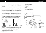
2.2.1 For easy and quick installation of the satellite dish, find a position on the roof where
the supply and control box will be installed (see 2.3.1) .
2.2.2 With a 20 diameter hole cutter make a hole for the passage of the cables inside the
vehicle’s cabin.
2.2.3 Clean and remove any grease from the surface around the hole. Take the cable box
and make a hole in it so the M25 cable (which includes the sat cable and the internal
connection cable) can pass through.
2.2.4 Run the cables inside, through the hole previously made in the roof and fix the cable
firmly to the cable box with the bolt (supplied in the kit).
2.2.5 Apply a generous layer of polyurethane adhesive on the base of the box (use the
same type as that used for the fastening of the external unit). Position the box on the roof
close to the hole and press in order to ensure a good distribution and adhesion of the glue.
Run the cables securely along the roof (insert them into a cable channel in order to protect
them from UV rays) and bring the excess cables into the camper.
2.2.6 The cables must be fastened to the roof in order to prevent them from moving or
being caught by objects such as branches.
The external assembly of the satellite dish is now complete.
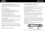
2.3 ASSEMBLY INSTRUCTIONS OF THE CONTROL BOX
2.3.1 Find a place inside the vehicle that is easily accessible to the user, preferably near
the TV or inside a cupboard.
2.3.2 Position and fasten the wall box inside this accessible and ventilated area so that
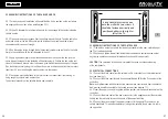
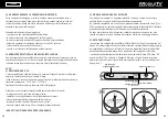
any service operations can be performed easily and quickly (see picture 5).
CAUTION! The ventilation of the device is important because it avoids overheating
of the components.
2.4 ELECTRICAL CONNECTIONS
2.4.1 Connect the black cable from the external unit to its terminals on the internal control
box (see drawing 7).
2.4.2 Connect the black coaxial cable from the satellite dish LNB to the F connector of the
control box.
Note: in satellite dishes with dual output, the second black coaxial cable from the satellite
dish must be directly connected to the second receiver (see drawing 7.1).
2.4.3 Insert the power connector supplied with the system into the special connector on the
control box.
2.4.4 Connect the black cable of the power connector to the negative pole of the domestic
battery and the red cable to the positive pole of the domestic battery.
2.4.5 Connect the green cable of the power connector to the special D+ position on the
vehicle dashboard. This enables automatic closing of the satellite dish in case it is left in
the up position.
2.3.1
Find a place inside the vehicle that is easily accessible to the user, preferably near
the TV or inside a cupboard.
2.3.2
Position and fasten the wall box inside this accessible and ventilated area so that
any service operations can be performed easily and quickly (see picture 5).
CAUTION!
The ventilation of the device is important because it avoids overheating
of the components.
5
It is advisable to fasten the box
onto the wall with two screws. It
should be fastened vertically and
positioned either to the right or
left of the TV.
2.3 Assembly instructions of the control box
9
GB
2


