


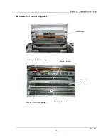


Chapter 2 Installation and Setup
TDP-324
-14-
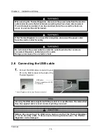
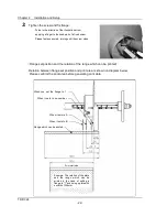
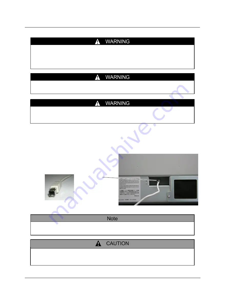
2.6 Connecting the USB cable
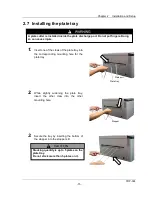
1.
Connect the USB cable connected to your
PC to the USB terminal at the back of the
Thermal Digiplater
When moving the Thermal Digiplater, disconnect the power cable from the electric
outlet and make sure that all external connecting lines have been disconnected.
If a cord is kept connected, it can be scratched, and a fire or electric shock can
occur, or you can trip and be injured.
If the Thermal Digiplater is not used for a long time, disconnect the power cable
from the electric outlet for safety.
Do not connect the power cable to an electric outlet to which other cords are
connected. Requires a dedicated electric outlet.
Doing so can cause a fire or electric shock.
USB cable
[Product compatible with USB
2.0 standard]
Use only the USB cable supplied with the product or a specified one. If a cable other
than the supplied cable is used, incorrect printing can result.
Before disconnecting the USB cable, make sure that the Thermal Digiplater
is in the standby
state. If disconnected during data transfer, the Thermal
Digiplater can be damaged.
Thermal Digiplater side is a type B connector(square)
Содержание TDP-324
Страница 1: ......
Страница 2: ......
Страница 4: ......
Страница 54: ...Chapter 3 Use of Operation Panel TDP 324 48 MEMO...
Страница 72: ...Chapter 4 Daily Maintenance TDP 324 66 MEMO...
Страница 82: ...Chapter 7 After sales service TDP 324 76 MEMO...
Страница 84: ...Chapter 7 After sales service TDP 324 78 MEMO...


