Mitsubishi RV-2F Series Скачать руководство пользователя страница 72

5-63   

Maintenance and inspection procedures

5 Maintenance and Inspection

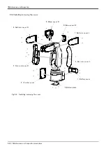
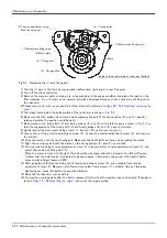
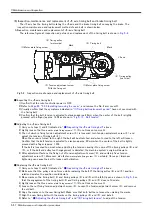
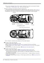
(8) Timing belt tension

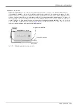
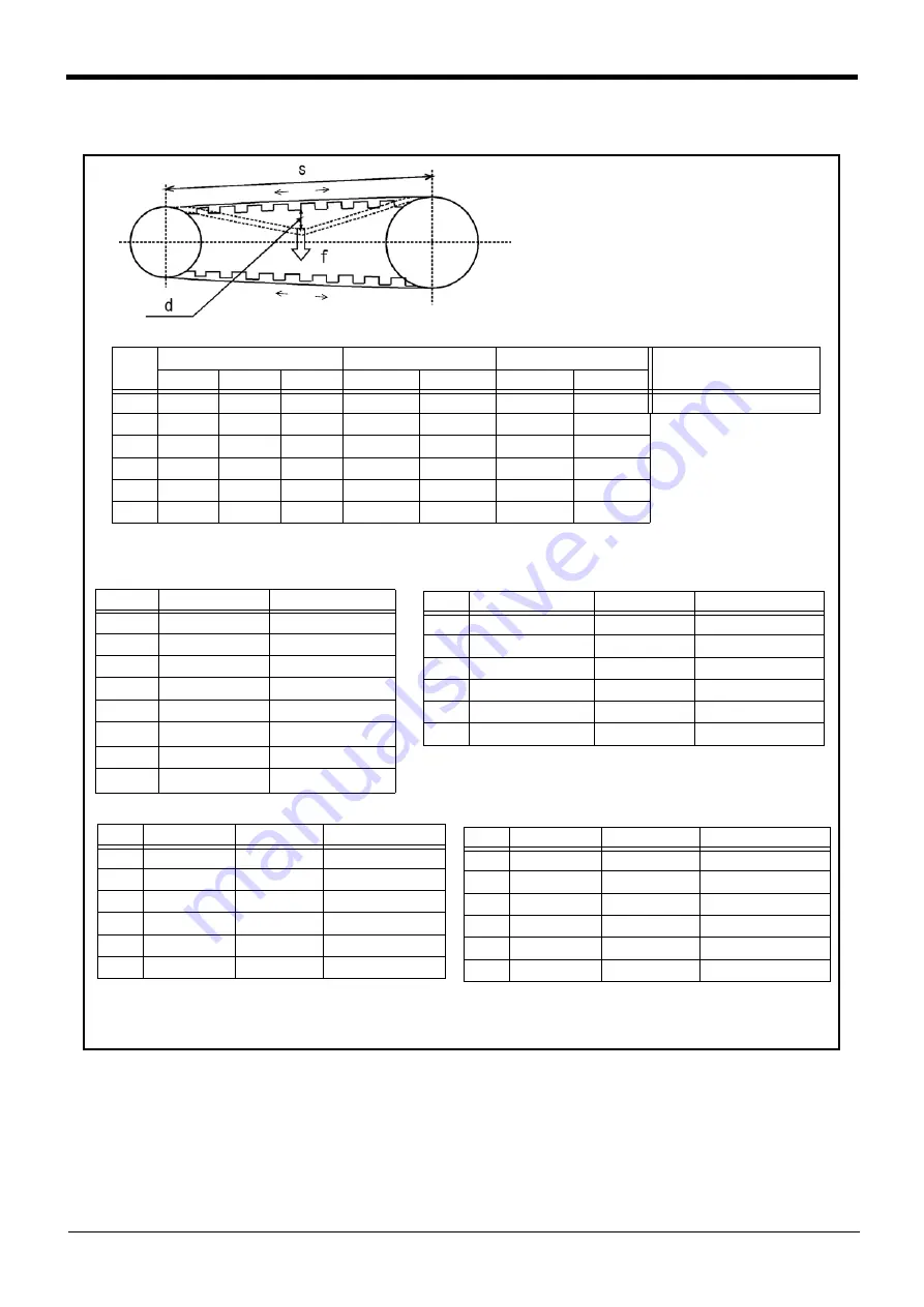
Fig.5-13 : Belt tension

The timing belt can satisfactorily convey the drive and keep a durable force only when it has an adequate tension. 

The belt tension should not be too tight or too loose. Instead, it should be adjusted to a degree that elasticity is 
felt when the belt is pressed with the thumb. If the belt tension is too weak, the belt loosening side will vibrate. On 
the other hand, if the belt tension is too strong, a sharp sound will be heard and the belt tension side will vibrate.

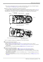
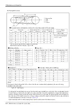
The detailed adjustment (tension) is shown in 

Fig. 5-13

.

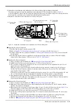
Check and adjust with the belt pressing force f and the slack amount d between span s.

T

T

T

T

 f : Pressing force
 s : Span
 d : Slack
 T : Tension

■ Belt specification

Axis

Belt type

Span : s (mm)

J1

210-3GT-6

61

J2

324-3GT-6

88

J3

303-3GT-6

103

J4

186-3GT-4

52

J5

336-3GT-4

131

J5(brake)

174-3GT-4

42

J6

345-3GT-4

131

J5(brake)

174-3GT-4

42

■ Inspection

Axis

Tension

: T (N)

Slack : d (mm)

Pressing force : f (N)

J1

14.7 ~ 43

1.0

1.0 ~ 2.9

J2

14.7 ~ 43

1.4

1.0 ~ 2.9

J3

14.7 ~ 43

1.6

1.0 ~ 2.9

J4

10 ~ 30

0.8

0.7 ~ 2

J5

10 ~ 30

2.0

0.7 ~ 2

J6

10 ~ 30

2.0

0.7 ~ 2

■ Exchange (New article installation)

Axis

Tension : T (N)

Slack : d (mm)

Pressing force : f (N)

J1

40

1.0

2.7

J2

40

1.4

2.7

J3

40

1.6

2.7

J4

28

0.8

1.9

J5

28

2.0

1.9

J6

28

2.0

1.9

■ The preset value and adjustment value in the sound wave type belt tension gauge

The sound wave type belt tension gauge of the standard
Maker:Gates Unitta Asia Company, Type:U-505

Axis

Preset value

Tension: Used belt (N)

Tension: New belt (N) 

Force of pulling the 

motor plate 

note 1)


wait

width

span

Minimum

Maximum

Minimum

Maximum

J1

2.5

6

61

26

32

37

43

31(N) ~ 39(N)

J2

2.5

6

88

26

32

37

43

Note 1) The force when pulling the 
motor plate for belt adjustment of 
the J1 axis is shown. 

J3

2.5

6

103

26

32

37

43

J4

2.5

4

52

18

22

26

30

J5

2.5

4

131

18

22

26

30

J6

2.5

4

131

18

22

26

30

■ Adjustment

Axis

Tension : T (N) Slack : d (mm) Pressing force : f (N)

J1

29

1.0

1.9

J2

29

1.4

1.9

J3

29

1.6

1.9

J4

20

0.8

1.3

J5

20

2.0

1.3

J6

20

2.0

1.3

<Note>
The tension of brake timing belt of the J5 and the J6 axis is automatically adjusted by the work of spring 
installed in the motor plate.

Содержание RV-2F Series

Страница 1: ...Mitsubishi Industrial Robot RV 2F Series INSTRUCTION MANUAL ROBOT ARM SETUP MAINTENANCE BFP A8904 C...

Страница 2: ......

Страница 3: ...on the start switch etc This also applies to maintenance work with the power source turned ON Indication of teaching work in progress Provide a fence or enclosure during operation to prevent contact...

Страница 4: ...this could lead to malfunctioning by noise or to electric shock accidents Indicate the operation state during robot operation Failure to indicate the state could lead to operators approaching the rob...

Страница 5: ...hub LAN hub etc confirmed by manufacturer The thing unsuitable for the FA environment related with conformity temperature or noise exists in the equipments connected to USB When using network equipme...

Страница 6: ...error in writing The notes about installation of the controller and the robot arm were added neither direct rays nor the heat of lighting 2012 11 19 BFP A8904 B The lithium battery type was added to...

Страница 7: ...series The specification in which all axes have the brake is included No part of this manual may be reproduced by any means or in any form without prior consent from Mitsubishi The details of this man...

Страница 8: ...ata 2 15 2 Turning ON the control power 2 15 3 Preparing the T B 2 16 4 Selecting the origin setting method 2 17 5 Inputting the origin data 2 18 6 Installing the J1 motor cover 2 19 2 4 Confirming th...

Страница 9: ...per method 5 71 1 J1 axis origin setting mechanical stopper 5 71 2 J2 axis origin setting mechanical stopper 5 73 3 J3 axis origin setting mechanical stopper 5 75 4 J4 axis origin setting mechanical s...

Страница 10: ...onfirmation of operation and the maintenance and inspection procedures Explains the procedures required to operate the controller unpacking transportation installation confirmation of operation basic...

Страница 11: ...Stand alone type Controller Indicates the box which arranged control parts such as robot CPU servo amplifier and the safety circuit Symbol Precaution indicating cases where there is a risk of operato...

Страница 12: ...work This also applies to maintenance work with the power source turned ON Setting of emergency stop switch During teaching work place a sign indicating that teaching work is in progress on the start...

Страница 13: ...uries or damage if the object comes off or flies off during operation Securely ground the robot and controller Failure to observe this could lead to malfunctioning by noise or to electric shock accide...

Страница 14: ...ot installed there is a possibility of malfunctioning by adhesion of the dust etc Don t remove the SSCNETIII cable when the power supply of the robot controller is turned on Don t face squarely the li...

Страница 15: ...pecifications Table 2 1 Standard configuration No Part name Type Qty Remarks 1 Robot arm RV 2F series 1 unit 2 Guarantee card 1 copy 3 Installation bolts M8x35 4 pcs 4 Spring washer for installation b...

Страница 16: ...process is shown below 1 The cardboard box is toppled over horizontally slowly Take care so that a shock may not be given Fig 2 1 a 2 Using a knife etc slit the tape fixing the upper lid of the cardbo...

Страница 17: ...lower section of elbow B Please be sure to avoid holding the robot from the front back side or by the cover because the robot may tilt over and the cover may be damaged or dropped which may lead to ac...

Страница 18: ...and the arm reaction during operation and resistance against deformation and vibration caused by the static dynamic load of the robot arm and peripheral devices etc 6 Remove the fixing plates after in...

Страница 19: ...grounding point should be as close to the robot arm and controller as possi ble and the length of the grounding wire should be short Fig 2 4 Grounding methods 2 Grounding procedures 1 Prepare the grou...

Страница 20: ...s fixed when the latch is released Please connect the connector securely If it inserts by force the pin will break And it becomes the cause of failure The machine cable connectors are dedicated for th...

Страница 21: ...y 4 Connects the machine cable to the corresponding connectors AMP1 AMP2 BRK and CN2 of the controller Fixes each connector by tightening the screws This completes connecting the machine cables Please...

Страница 22: ...it out Please do not pull the cable of T B strongly or do not bend it too much It becomes the breaking of a wire of the cable and the cause of breakage of the connector Please installing and removing...

Страница 23: ...Fig 2 9 Fig 2 9 Installing and removing the T B CR751 The installation of T B is finished A T B T B A 2 Controller T B connector Teaching pendant Details of the A section A Hand lock Two places T B co...

Страница 24: ...input is found on also the robot examination report sheet Always install remove the cover with the controller control power turned OFF Failure to do so could lead to physical damage or personal injury...

Страница 25: ...ABLE The menu selection screen will appear The following operations are carried out with the T B ENABLE DISABLE Up Disable Down Enable Lighting MODE MANUAL AUTOMATIC Operating from the T B Always set...

Страница 26: ...BRK 5 SET INIT 6 ENHANCED CLOSE 123 ORIGIN BRAKE 1 ORIGIN 2 BRAKE CLOSE 123 ORIGIN 1 DATA 2 MECH 3 TOOL 4 ABS 5 USER CLOSE 123 ORIGIN DATA D J1 J2 J3 J4 J5 J6 J7 J8 CLOSE 123 Selecting a menu The menu...

Страница 27: ...he key five times will be set Press the key once and advance the cursor Press the key twice input and press the PQRS key four times input S Press the CHARACTER key and set to the numeral input mode Co...

Страница 28: ...V S29 J1 06DTYY J2 2 HL9X J3 1CP55V J4 T6 MSY J5 Z21J Z J6 A12 Z0 J7 J8 CLOSE ABC ORIGIN DATA CHANGE TO ORIGIN OK No 123 Yes Moving the cursor Press the and keys Inputting characters Press the CHARAC...

Страница 29: ...ators near the robot and that there are no obstacles such as tools in the robot operation range To immediately stop the robot release the deadman switch on the back of the T B The servo power will tur...

Страница 30: ...ure the axis moves straight along the base coordinate system Also while maintaining the flange surface position the flange surface posture changes Control point X Y Z While maintaining the flange surf...

Страница 31: ...lange surface position does not change at this time It is effective to change the posture of the wrist with the position maintained J4 axis J5 axis J6 axis X Y Z Z The current position is set as the a...

Страница 32: ...og operation X Y Z Xw Yw Zw Zw Xw Yw While maintaining the flange surface posture the axis moves straight along the work coordinate system Also while maintaining the flange surface position the flange...

Страница 33: ...pond to close Whenever it presses the key of OVRD the override goes up Conversely if the OVRD key is pressed it will go down The current setting speed is displayed on screen upper right and STATUS NUM...

Страница 34: ...ate in the minus direction When the Z J3 keys are pressed the J3 axis will rotate in the plus direction When the Z J3 keys are pressed Rotate in the minus direction J2 axis jog operation When the robo...

Страница 35: ...the B J5 keys are pressed Rotate in the minus direction When the C J6 keys are pressed the J6 axis will rotate in the plus direction When the C J6 keys are pressed Rotate in the minus direction J6 J5...

Страница 36: ...s direction When the X J1 keys are pressed Move along the minus direction When the Y J2 keys are pressed the robot will move along the Y axis plus direction When the Y J2 keys are pressed Move along t...

Страница 37: ...sounds and the robot does not move If it is going to move the robot across the operation range the buzzer of T B sounds and the robot does not move In this case please move to the counter direction X...

Страница 38: ...en the X J1 keys are pressed Move along the minus direction When the Y J2 keys are pressed the robot will move along the Y axis plus direction of the tool coordinate system When the Y J2 keys are pres...

Страница 39: ...in the minus direction If the buzzer of T B sounds and the robot does not move If it is going to move the robot across the operation range the buzzer of T B sounds and the robot does not move In this...

Страница 40: ...d the robot will move along the X axis plus direction When the X J1 keys are pressed Move along the minus direction When the Y J2 keys are pressed the robot will move along the Y axis plus direction W...

Страница 41: ...he B J5 keys are pressed the J5 axis will rotate in the plus direction At this time to maintain the flange s position other axes move simultaneously except J4 and J6 When the B J5 keys are pressed Rot...

Страница 42: ...10 here for confirmation work Assuming that the current position is on an arc centering on the Z axis the robot moves along that arc When the X J1 keys are pressed the robot will expand in the radial...

Страница 43: ...J5 keys are pressed The Y axis will rotate in the plus direction When the B J5 keys are pressed Rotate in the minus direction When the C J6 keys are pressed The Z axis will rotate in the plus directio...

Страница 44: ...hing point The setting definition method of the work coordinates system is shown in the following 1 Select 6 ENHANCED screen on the MENU screen Zw Xw Yw Z Y X Teaching point WO Work coordinates system...

Страница 45: ...sponding to TEACH F1 The confirmation screen is displayed The screen shows the coordinate value of the origin WO of the work coordinates number 1 EMHANCED 1 SQ DIRECT 2 WORK COORD CLOSE 123 WORK COORD...

Страница 46: ...re teach the three points This work coordinate data is registered into parameter WKnCORD n means the work coordinates numbers 1 8 If the function key corresponding to CLOSE is pressed it will return...

Страница 47: ...s confirm that the number of the target work coordinates system is displayed correctly Display of W1 W8 at the upper right of the screen If mistaken the robot will move in the direction which is not m...

Страница 48: ...he work coordinates system When the Y J2 keys are pressed Move along the minus direction When the Z J3 keys are pressed the robot will move along the Z axis plus direction on the work coordinates syst...

Страница 49: ...in accordance with the work coordinates system Work coordinates system Tool length Controll point When the robot is in the transportation posture There are directions from which linear movement is no...

Страница 50: ...noid valve with the enclosed screw 1 M3 x 25 2 screws 2 Connect the primary air supply air hose 6 prepared by customer to the quick joint P port 2 of the solenoid valve 1 4 2 4 1 1 GR1 GR4 AIR OUT 1 2...

Страница 51: ...econdary coupler to the A port 7 of the No 2 solenoid valve 6 Connect the AIR IN 4 mark secondary coupler to the B port 8 of the No 2 solenoid valve 6 4 Connect the GR1 plug from the No 1 solenoid val...

Страница 52: ...ons 4 Basic operations The basic operations from creating the program to automatic operation are explained in section 4 Basic operations in the From Controller Setup to Maintenance manual Refer that m...

Страница 53: ...0 Hr operation hours Fig 5 1 Inspection schedule 0 Hr Daily inspection Monthly inspection Monthly inspection 500 Hr Monthly inspection 3 month inspection Monthly inspection Monthly inspection 1 000 Hr...

Страница 54: ...troller securely connected Visual Securely connect 6 Are there any cracks foreign contamination or obstacles on the robot and controller cover Replace with a new part or take remedial measures 7 Is th...

Страница 55: ...abnormal If the timing belt is loose or too tense adjust it 6 month inspection items 1 Is the friction at the timing belt teeth severe If the teeth are missing or severe friction is found replace the...

Страница 56: ...tic brakes are mounted in the J2 axis motor 3 The rotation of the J3 axis motor 7 arranged in the No 1 arm is conveyed to the reduction gears 9 via the timing belt 8 to rotate the J3 axis Non excitati...

Страница 57: ...xis motor 7 J3 axis motor 10 J4 axis motor 20 Gear 13 J5 axis motor 14 Timing belt 16 Reduction gears 18 J6 axis motor 3 Reduction gears 21 Reduction gears 2 Timing belt 11 Timing belt 17 J5 axis brak...

Страница 58: ...nance and Inspection 5 3 2 Installing removing the cover Fig 5 3 Installing removing the cover 6 Elbow cover R 5 Elbow cover B 8 No 2 arm cover R 7 No 2 arm cover L 4 No 1 arm cover L 3 No 1 arm cover...

Страница 59: ...ttaching the cover after maintenance and inspection use the detaching procedure in reverse The part No and symbols in Table 5 3 correspond to Fig 5 3 No Cover names Qty Installation screw 1 Battery co...

Страница 60: ...adjust and replace if necessary In addition it is serviceable if there is the sound wave type belt tension gauge in inspection and adjustment of the timing belt The recommendation gauge is shown below...

Страница 61: ...o motor plate fixing screws 1 Improper tightening can cause the belt to loosen with vibration If the belt is loosened too much when adjusting the tension causing it to come off the timing pulleys 4 an...

Страница 62: ...Loosen the tension adjustment screw 3 and remove the old belt 10 Copy the marks onto the new timing belt Make sure that both belts are tense when making the marks 11 Align the new timing belt with the...

Страница 63: ...timing pulleys 4 and 5 or if the belt and pulley teeth engagement is deviated the machine system s origin will deviate 4 After adjustment fastens the fixing nut of tension adjustment screw 3 and cert...

Страница 64: ...ming pulleys 4 and 5 or if the belt and pulley teeth engagement is deviated the machine system s origin will deviate 4 After adjustment fastens the fixing nut of tension adjustment screw 3 and certain...

Страница 65: ...ming pulleys 4 and 5 or if the belt and pulley teeth engagement is deviated the machine system s origin will deviate 4 After adjustment fastens the fixing nut of tension adjustment screw 3 and certain...

Страница 66: ...e belt tension is adjusted to slacken approx 2 0mm when the center of the belt is lightly pressed with a finger approx 1 3N If the belt is loosened too much when adjusting the tension causing it to co...

Страница 67: ...the cover and remove the No 2 arm cover R and L 3 Visually confirm that the symptoms indicated in 1 Timing belt replacement period have not occurred with the timing belt 4 Adjust the tension of the be...

Страница 68: ...much 4 Move motor side timing belt pulley 4 in the direction of the arrow a of Fig 5 10 and remove the brake timing belt 5 Install the new brake timing belt The operations of matching the position fo...

Страница 69: ...is adjusted to slacken approx 2 0mm when the center of the belt is lightly pressed with a finger approx 1 3N If the belt is loosened too much when adjusting the tension causing it to come off the tim...

Страница 70: ...ing the cover and remove the No 2 arm cover R and L 3 Visually confirm that the symptoms indicated in 1 Timing belt replacement period have not occurred with the timing belt 4 Adjust the tension of th...

Страница 71: ...much 4 Move motor side timing belt pulley 4 in the direction of the arrow a of Fig 5 12 and remove the brake timing belt 5 Install the new brake timing belt The operations of matching the position fo...

Страница 72: ...T N Slack d mm Pressing force f N J1 14 7 43 1 0 1 0 2 9 J2 14 7 43 1 4 1 0 2 9 J3 14 7 43 1 6 1 0 2 9 J4 10 30 0 8 0 7 2 J5 10 30 2 0 0 7 2 J6 10 30 2 0 0 7 2 Exchange New article installation Axis T...

Страница 73: ...il maker Default charge amount Lubrication interval Lubrication amount Cover to remove 1 J1 axis reduction gears Grease nipple WA 610 Grease Harmonic grease SK 1A Japan Harmonic Systems 11 9g 6 000Hr...

Страница 74: ...er and remove the covers 3 Please protect the timing belt with the cloth etc so that the grease does not take for the timing belt at the time of oil supply 4 J5 axis lubrication port 5 the J6 axis lub...

Страница 75: ...the controller simultaneously Table 5 5 The error about the battery The method of replacing the battery of robot arm is shown below refer to the separate Instruction manual Controller setup basic ope...

Страница 76: ...is a measure for safety and must always be carried out 4 Remove battery cover 1 referring to Page 49 5 3 2 Installing removing the cover 5 The battery holder is located in the battery cover 1 Remove...

Страница 77: ...aries with their operating conditions and thus with the degree of the equipment s wear and loss of performance As a rule of thumb however it is recommended that overhaul be carried out before the tota...

Страница 78: ...troller serial No and purchase the parts from the dealer Table 5 6 Consumable part list Table 5 7 Spare parts list No Part name Type Usage place Q ty Supplier 1 Timing belt J1 axis Mitsubishi Electric...

Страница 79: ...Origin data input method The origin data set as the default is input from the T B The setting method is explained in Page 13 2 3 Setting the origin 2 Mechanical stopper method This origin posture is...

Страница 80: ...n the menu screen and dis play the Origin BRK selection screen 2 The type which does not have the brake in the J1 axis should go to 6 8 Press the 2 key and display the Break release selection screen 3...

Страница 81: ...RIGIN BRAKE 1 ORIGIN 2 BRAKE CLOSE 123 ORIGIN 1 DATA 2 MECH 3 TOOL 4 ABS 5 USER CLOSE 123 ORIGIN MECH J1 1 J2 J3 J4 J5 J6 J7 J8 CLOSE 123 ORIGIN MECH COMPLETED J1 1 J2 J3 J4 J5 J6 J7 J8 CLOSE 123 ORIG...

Страница 82: ...kept with the enabling switch of T B pressed down The brake is released while pressing the key 6 With both hands slowly move the J2 axis in minus direction and contact the axis against the mechanical...

Страница 83: ...R CLOSE 123 ORIGIN MECH J1 J2 1 J3 J4 J5 J6 J7 J8 CLOSE 123 ORIGIN MECH CHANGE TO ORIGIN OK No 123 Yes ORIGIN MECH COMPLETED J1 J2 1 J3 J4 J5 J6 J7 J8 CLOSE 123 Release the brake Do cursor movement in...

Страница 84: ...is kept with the enabling switch of T B pressed down The brake is released while pressing the key 6 With both hands slowly move the J3 axis in plus direction and contact the axis against the mechanica...

Страница 85: ...R CLOSE 123 ORIGIN MECH J1 J2 J3 1 J4 J5 J6 J7 J8 CLOSE 123 ORIGIN MECH CHANGE TO ORIGIN OK No 123 Yes ORIGIN MECH COMPLETED J1 J2 J3 1 J4 J5 J6 J7 J8 CLOSE 123 Release the brake Do cursor movement in...

Страница 86: ...th the enabling switch of T B pressed down The brake is released while pressing the key 6 With both hands slowly move the J4 axis in plus direction and contact the axis against the mechanical stopper...

Страница 87: ...J3 J4 1 J5 J6 J7 J8 CLOSE 123 ORIGIN MECH CHANGE TO ORIGIN OK No 123 Yes ORIGIN MECH COMPLETED J1 J2 J3 J4 1 J5 J6 J7 J8 CLOSE 123 Release the brake Do cursor movement into the parenthesis of each axi...

Страница 88: ...e brakes are to be released 5 Pressing the F1 key is kept with the enabling switch of T B pressed down The brake is released while pressing the key 6 With both hands slowly move the J5 axis in plus di...

Страница 89: ...he brake is released while pressing the key 11 Hold the bolts with hands rotate them slowly and align the ABS mark of the J6 axis with the ABS mark of the wrist area 12 If the ABS mark is aligned deta...

Страница 90: ...OSE 123 ORIGIN MECH J1 J2 J3 J4 J5 1 J6 1 J7 J8 CLOSE 123 SPACE ORIGIN MECH CHANGE TO ORIGIN OK No 123 Yes Release the brake Do cursor movement into the parenthesis of each axis by the arrow key The b...

Страница 91: ...position There are the method of releasing the brake and adjusting with the origin position manually and the method of adjusting with the origin position by jog feed Here explain operation by brake re...

Страница 92: ...nt using both hands Align the pinhole of the No 1 arm and the pinhole at the base section feed through the origin jig 6 into the pinholes and fasten 7 Detach the F1 key and work the brake Press the F4...

Страница 93: ...1 1 J2 0 J3 0 J4 0 J5 0 J6 0 J7 0 J8 0 CLOSE 123 REL SPACE ORIGIN TOOL CHANGE TO ORIGIN OK No 123 Yes TOOL J1 1 J2 0 J3 0 J4 0 J5 0 J6 0 J7 0 J8 0 CLOSE 123 REL COMPLETED Release the brake Do cursor m...

Страница 94: ...ly toward the front using both hands Align the pinhole of the No 1 arm and the pinhole at the base section feed through the origin jig 6 into the pinholes and fasten For safety purposes the step for r...

Страница 95: ...AKE CLOSE 123 ORIGIN 1 DATA 2 MECH 3 TOOL 4 ABS 5 USER CLOSE 123 SPACE TOOL J1 1 J2 0 J3 0 J4 0 J5 0 J6 0 J7 0 J8 0 CLOSE 123 REL 0 1 ORIGIN TOOL CHANGE TO ORIGIN OK No 123 Yes TOOL J1 1 J2 0 J3 0 J4...

Страница 96: ...ly toward the front using both hands Align the pinhole of the No 1 arm and the pinhole at the base section feed through the origin jig 6 into the pinholes and fasten For safety purposes the step for r...

Страница 97: ...KE CLOSE 123 ORIGIN 1 DATA 2 MECH 3 TOOL 4 ABS 5 USER CLOSE 123 SPACE TOOL J1 1 J2 0 J3 0 J4 0 J5 0 J6 0 J7 0 J8 0 CLOSE 123 REL 1 0 ORIGIN TOOL CHANGE TO ORIGIN OK No 123 Yes TOOL J1 1 J2 0 J3 0 J4 0...

Страница 98: ...sing the F1 key is kept with the enabling switch of T B pressed down The brake is released while pressing the key 7 Slowly rotate the J4 axis in the direction of minus with both hands Align the pinhol...

Страница 99: ...J2 0 J3 0 J4 0 J5 0 J6 0 J7 0 J8 0 CLOSE 123 REL 1 0 ORIGIN TOOL CHANGE TO ORIGIN OK No 123 Yes TOOL J1 1 J2 0 J3 0 J4 0 J5 0 J6 0 J7 0 J8 0 CLOSE 123 REL COMPLETED 1 0 Release the brake Do cursor mo...

Страница 100: ...ssing the F1 key is kept with the enabling switch of T B pressed down The brake is released while pressing the key 8 Slowly rotate the J5 axis in the direction of plus 90 degree with both hands Align...

Страница 101: ...eleased 12 Pressing the F1 key is kept with the enabling switch of T B pressed down The brake is released while pressing the key 13 Hold the bolts with hands rotate them slowly and align the ABS mark...

Страница 102: ...23 REL SPACE ORIGIN BRAKE 1 ORIGIN 2 BRAKE CLOSE 123 ORIGIN 1 DATA 2 MECH 3 TOOL 4 ABS 5 USER CLOSE 123 TOOL COMPLETED J1 0 J2 0 J3 0 J4 0 J5 1 J6 1 J7 0 J8 0 CLOSE 123 REL ORIGIN TOOL CHANGE TO ORIGI...

Страница 103: ...E switch on the teaching pendant to ENABLE to enable the teaching pendant First set to the ABS mark arrow of the axis for which the origin is to be set with jog operation This can be set for all axes...

Страница 104: ...lection screen 4 Input 1 into the axis to origin setting Press the EXE key and display Confirmation screen Note Always perform origin setting of the J5 axis and the J6 axis simultaneously 5 Press the...

Страница 105: ...Confirming the operation for details on the jog operation Choose the user origin position as the position where it doesn t move by the gravity This position is left as a guideline to position all axes...

Страница 106: ...o origin setting Press the EXE key and display Confirmation screen 9 Press the F1 key and the origin position is set up This complete the Origin setting by the User origin method USER J1 1 J2 0 J3 0 J...

Страница 107: ...1 Confirming the origin data label Remove the J1 motor cover Refer to Page 49 5 3 2 Installing removing the cover and remove the J1 motor cover 2 Confirming the origin data Confirm the value displayed...

Страница 108: ...in the position constant X Y Z A B C FL1 FL2 The types of configuration flags are shown below 1 RIGHT LEFT Q is center of J5 axis rotation in comparison with the plane through the J1 axis vertical to...

Страница 109: ...This means in which side the J6 axis is in comparison with the plane through both the J4 and the J5 axis Fig 6 3 Configuration flag NONFLIP FLIP J4 axis J6 axis flange surface FLIP NON FILIP FL1 Flag...

Страница 110: ...Appendix 101 Configuration flag 6Appendix...

Страница 111: ...without notice HEAD OFFICE TOKYO BUILDING 2 7 3 MARUNOUCHI CHIYODA KU TOKYO 100 8310 JAPAN NAGOYA WORKS 5 1 14 YADA MINAMI HIGASHI KU NAGOYA 461 8670 JAPAN Authorised representative MITSUBISHI ELECTRI...

Страница 112: ...oie 37 FIN 28400 Ulvila Phone 358 0 207 463 540 Fax 358 0 207 463 541 GREECE UTECO 5 Mavrogenous Str GR 18542 Piraeus Phone 30 211 1206 900 Fax 30 211 1206 999 HUNGARY AXICONT AUTOMATIKA Kft ROBOT CEN...

Отзывы: