


1. OUTLINE
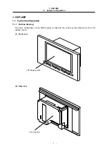
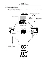
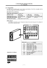
1.1 System Configuration
– 3 –
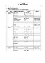
1.1.3 Configuration
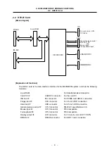
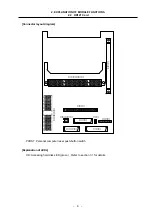
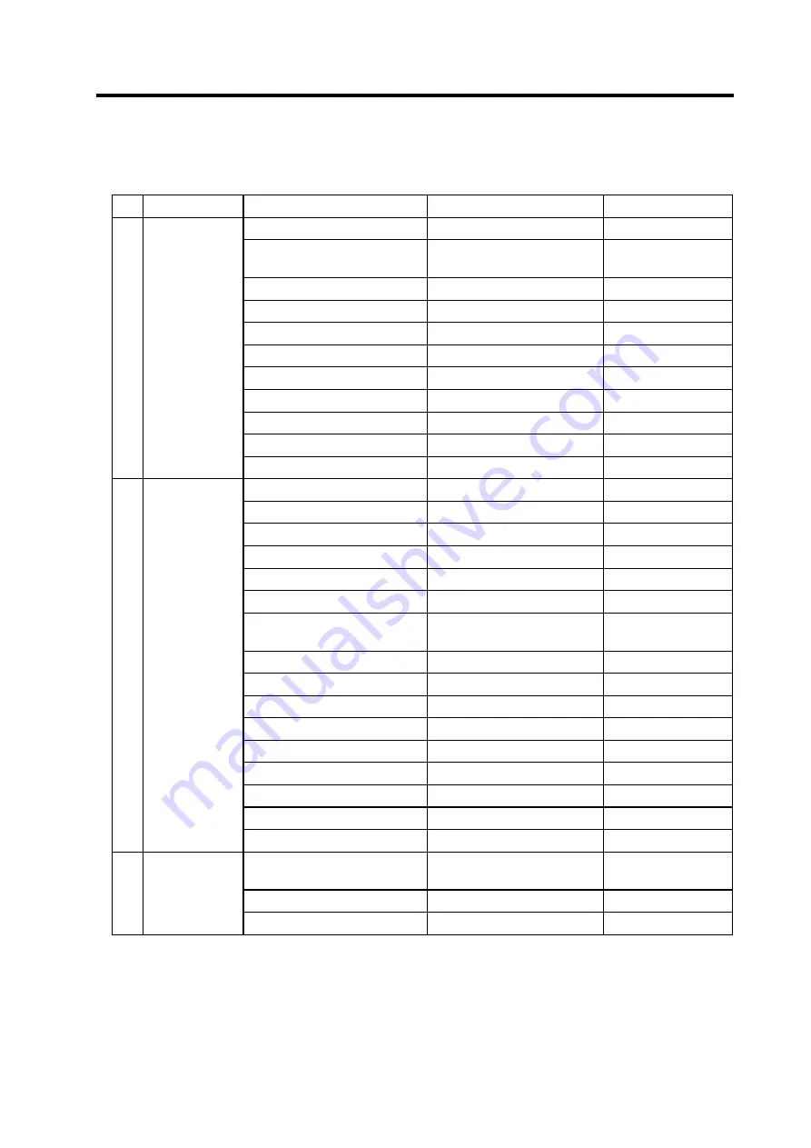
(1) Module configuration table
The M600 system is configured of the modules shown below.
No.
Type
Configuration module type
Function
Remarks
1
HR111 card
Main CPU card
Control section
6MU001
HR121 card
Man-machine interface
card
HR081 card
Control power supply card
CARD PC
Man-machine
Mounted on HR121
ER6 BKO-NC2157H01
Battery
Mounted on HR081
MMF-04B05DM-R
DC fan
Mounted on HR111
Chassis
Aluminum die cast
Frame
Molded resin part
Cover
Molded resin part
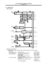
2
KCS6448HSTT-X3
LCD STN display
Display section
6MB201
HR273 card
STN signal relay PCB
KCI-04
Backlight power supply
F082 cable
HR081- backlight power
supply
F090
cable
HR121-HR273
F091
cable
HR273-LCD
F092
cable
HR273-LCD
KS-6MB201A-P
Menu
keys
Escutcheon
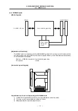
3
HR841 card
PCMCIA I/F
Built-in control
section
PCMCIA I/F
6PCM01
F150
cable
HR121-HR841