


4. DAILY MAINTENANCE AND PERIODIC INSPECTION AND MAINTENANCE
4.3 Replacement Methods
– 49 –
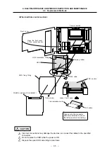
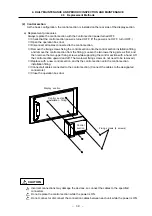
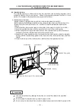
(5) Expansion
PCB
The expansion PCB is used to expand the system for adding a serial port, etc. (Refer to
corresponding modules in section 1.1.3 and section 2, for details on the expansion PCB types
and functions.)
Up to two expansion PCBs can be added. The PCBs are mounted in the slots on the right side of
the control section power supply PCB.
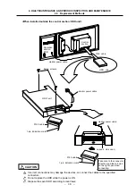
a) Replacement procedures
Always replace the expansion PCB with the control section power turned OFF.
①
Check that the control section power is turned OFF. (If the power is not OFF, turn it OFF.)
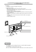
②
Open the operation box door, and then open the front cover of the control section.
③
Disconnect all cables connected to the expansion PCB.
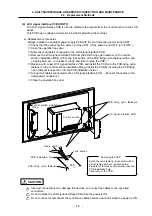
④
While holding the front upper and lower sections of the expansion PCB with both hands, pull
out the PCB from the control section.
⑤
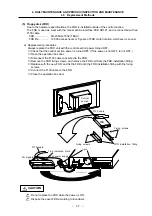
Replace with a new expansion PCB, and if the PCB has settings, set the settings to the same
as the original PCB.
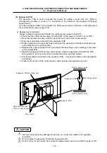
⑥
Install the expansion PCB into the control section. (Align the expansion PCB with the PCB
fixing guides on the inner side of the control section case, and then install.)
⑦
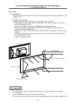
Connect all cables connected to the expansion PCB. (Connect the cables to the designated
connectors.)
⑧
Close the front cover of the control section, and then close the operation box door.
Expansion PCB mounting slot
Open the front cover
of the control section.
Front cover
Control section case
Expansion PCB
PCB fixing guides
Control section case
Expansion PCB
Control section
Incorrect connections may damage the devices, so connect the cables to the specified
connectors.
Do not replace the expansion PCB while the power is ON.
Do not connect or disconnect the connection cables between each unit while the power is ON.
CAUTION