


4. DAILY MAINTENANCE AND PERIODIC INSPECTION AND MAINTENANCE
4.3 Replacement Methods
– 48 –
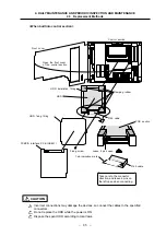
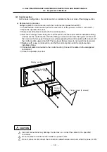
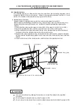
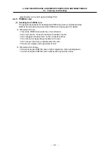
(4) LCD signal interface PCB (HR273)
The LCD signal interface PCB is used to distribute the signals from the control section to the LCD
panel.
This PCB has a voltage booster circuit inside for adjusting the contrast.
a) Replacement procedures
Always replace the backlight power supply PCB with the control section power turned OFF.
①
Check that the control section power is turned OFF. (If the power is not OFF, turn it OFF.)
②
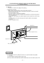
Open the operation box door.
③
Disconnect all cables connected to the LCD signal interface PCB.
④
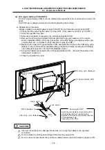
Remove the LCD signal interface PCB from the PCB fixing nylon fastener on the control
section installation fitting. (Pinch the lock section of the PCB fixing nylon fastener with a pair
of radio pliers, etc., to release the lock, and then remove the PCB.)
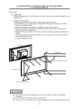
⑤
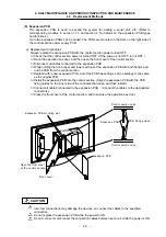
Replace with a new LCD signal interface PCB, and install the PCB onto the PCB fixing nylon
fastener on the control section installation fitting. (Install the PCB by inserting the PCB fixing
nylon fastener lock section into the PCB installation holes.)
⑥
Connect all cables connected to the LCD signal interface PCB. (Connect the cables to the
designated connectors.)
⑦
Close the operation box door.
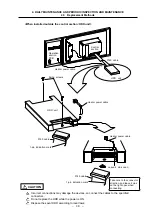
Control section installation
fitting
Control section
PCB fixing nylon fasteners
LCD signal interface PCB
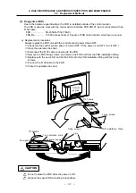
Radio pliers
PCB installation hole
PCB fixing nylon fastener
Lock section
PCB
Pinch the nylon fastener lock section with a
pair of radio pliers, etc., and make the
diameter of the lock section smaller than the
PCB installation hole.
Then remove the PCB.
Removing the PCB
Incorrect connections may damage the devices, so connect the cables to the specified
connectors.
Do not replace the LCD signal interface PCB while the power is ON.
Do not connect or disconnect the connection cables between each unit while the power is ON.
CAUTION