


4. DAILY MAINTENANCE AND PERIODIC INSPECTION AND MAINTENANCE
4.3 Replacement Methods
– 34 –
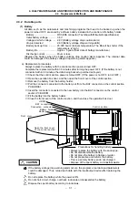
(4) Hard disk (HDD)
Depending on the hardware specifications, the HDD may be built into the control section or may
be installed externally. In either case, the HDD is connected to the control section PCB HR121
with an F140 cable.
HDD....................
MK1924FCV (Toshiba)
HDD life .............. 5 years or 20,000 power ON hours, whichever is sooner
HDD unit............. FCU6-HD101-1 (Mitsubishi Electric)
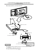
a) Replacement procedures
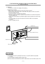
<When built into control section>
Always replace the HDD with the control section power turned OFF.
①
Check that the control section power is turned OFF. (If the power is not OFF, turn it OFF.)
②
Open the operation box door, and then open the front cover of the control section.
③
If the PCMCIA interface PCB HR841 is built into the control section, remove it.
(Refer to section
∗
.
∗
for the removal methods.)
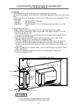
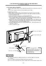
④
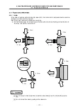
Disconnect the F140 cable connected to the control section PCB HR121.
⑤
Remove the HDD fixing fitting screws, and remove the HDD fixing fitting.
⑥
While holding the area near the right center of the HDD installation fitting, remove the HDD
with the installation fitting intact.
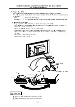
⑦
Remove the HDD from the HDD installation fitting. (Pull toward the top of the installation fitting.
Remove with the damping rubber intact.)
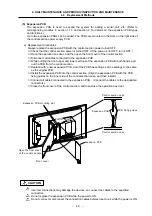
⑧
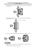
Disconnect the F140 cable from the HDD, and connect the F140 cable to the new HDD. (Take
care to the connection direction when installing.)
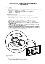
⑨
With the HDD PCB section facing upward, install the HDD onto the HDD installation fitting.
(Install the HDD onto the groove of the damping rubber installed on the HDD installation
fitting.)
⑩
Install the damping rubber between the tops of the HDD and HDD installation fitting. (Install
the damping rubber so that it fits securely into the positioning holes on the side of the HDD
installation fitting.)
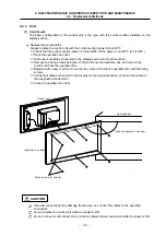
⑪
Install the HDD installation fitting onto the control section.
⑫
Install the HDD fixing fitting, and fix with the fixing screws. (Insert the HDD fixing fitting
between the HDD installation fitting and the claws on the left side of the control section case.
⑬
Connect the F140 cable from the HDD to the control section PCB HR121.
⑭
If the PCMCIA interface PCB HR841 is built into the control section, install it. (Refer to section
∗
.
∗
for the installation methods.)
⑮
Close the front cover of the control section, and then close the operation box door.
Refer to the replacement procedure diagram on page
∗
.
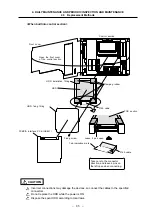
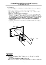
<When installed outside the control section: HDD unit>
Always replace the HDD unit with the control section power turned OFF.
①
Check that the control section power is turned OFF. (If the power is not OFF, turn it OFF.)
②
Open the operation box door.
③
Disconnect the heater power cable connected from the HDD unit to the operation section
PCB.
④
Disconnect the F140 cable connected to the HDD in the HDD unit. (Disconnect the F140
cable while supporting the front and rear of the HDD with fingers.)
⑤
Remove the HDD unit installation screws, and remove the HDD unit from the operation box.
⑥
Replace with the new HDD unit, and fix the HDD unit onto the operation box with the
installation screws.
⑦
Connect the F140 cable to the HDD in the HDD unit.
(Fix the F140 cable while supporting the front and rear of the HDD with fingers. Take care to
the direction.)
⑧
Connect the HDD unit heater power cable to the operation section PCB.
⑨
Close the operation box door.
Refer to the replacement procedure diagram on page
∗
.