MAINTENANCE MANUAL
BNP-B2189B (ENG)
M600 Series
Страница 1: ...MAINTENANCE MANUAL BNP B2189B ENG M600 Series...
Страница 2: ...n this manual WARNING 1 Items related to prevention of electric shocks Do not operate the switches with wet hands as this may lead to electric shocks Do not damage apply excessive stress place heavy t...
Страница 3: ...using a capacitive load such as a lamp always connect a protective resistor serially to the load to suppress rush currents Do not connect or disconnect the connection cables between each unit while th...
Страница 4: ...Tools 27 4 2 Maintenance Items 28 4 3 Replacement Methods 29 4 3 1 Cable 29 4 3 2 Durable parts 31 1 Battery 31 2 Backlight 32 3 Cooling fan 33 4 Hard disk HDD 34 5 Floppy disk FDD 37 4 3 3 Unit 38 1...
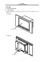
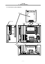
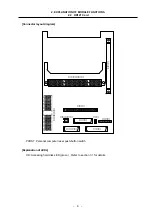
Страница 5: ...System Configuration 1 1 1 Outline drawing The basic configuration of the M600 system is that with the control section attached to the LCD display section 1 Front view LCD display section 2 Rear view...
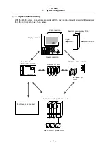
Страница 6: ...te I O separated from the control section as shown below I O INTERFACE HR325 327 335 337 HR371 24VDC 200VAC LCD Control section Display section Operation section External power supply PD25 Base I O un...
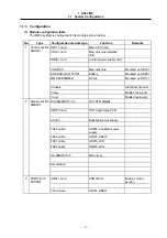
Страница 7: ...n machine Mounted on HR121 ER6 BKO NC2157H01 Battery Mounted on HR081 MMF 04B05DM R DC fan Mounted on HR111 Chassis Aluminum die cast Frame Molded resin part Cover Molded resin part 2 KCS6448HSTT X3 L...
Страница 8: ...heater Damping rubber 4 pieces 5 PD25 External power supply Single supply parts HR371 card Card sized I O Source method Di 16 points Do 16 points HR325 card Sink method Di 48 points Do 48 points HR335...
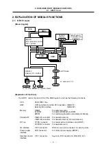
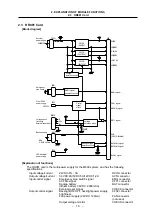
Страница 9: ...TLINE 1 1 System Configuration 5 2 Control section module configuration CARD HR841 card HR111 card HR121 card HR081 card HR121 card HR841 card PC card Expansion card Cassette memory F150 cable F150 ca...
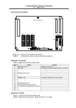
Страница 10: ...llowing functions CPU 64 bit RISC chip ASIC CPU peripheral control PLC operation MAC401 External I O interface MAC402 Memory DRAM For system working FLROM For system ROM boot ROM SRAM For machining pr...
Страница 11: ...on Explanation of settings NCSYS System mode selection rotary switch Switch Mode Details 0 Standard mode Operation of system 1 1 PLC stop The system is started while the PLC is stopped 2 3 4 5 6 Maint...
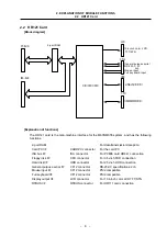
Страница 12: ...unctions 2 port RAM For data transmission reception Card PC I F CARDPC connector For the card PC ISA bus I F ISA connector For PCMIA card HR841 connection Floppy disk I F CFD connector For 3 5 inch FD...
Страница 13: ...LANATION OF MODULE FUNCTIONS 2 2 HR121 Card 9 Connector layout diagram PCRST Personal computer reset push button switch Explanation of LEDs HD Accessing hard disk LED green Refer to section 3 1 for de...
Страница 14: ...er supply From PD25 power supply Voltage check for testing ER6 3 6V 2 000mA Voltage detection circuit External reset input Explanation of functions The HR081 card is the multi power supply for the M60...
Страница 15: ...ut for LCD backlight EMG input ACFAIL input 24VDC input External reset input PSRST System reset do not press during normal system operation Explanation of LEDs DCIN LED lit during 24VDC supply green D...
Страница 16: ...card and ISA bus that comply with the PCMCIA Personal Computer Memory Card International Association 2 1 and JEIDA 4 2 standards ISA bus PCMCIA conversion bus controller gate array IC card slot 2 slot...
Страница 17: ...4V Output 26 to 28V STN LCD signal LCD connector HR121 side CN1 CN2 connector STN LCD side Contrast voltage output CN3 connector Contrast voltage fine VR1 The contrast voltage has been set before adj...
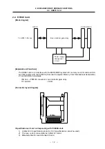
Страница 18: ...cabinet Up to eight remote cards can be connected per system The functions for each card are as follow MAC303 Remote I O controller Channel No data The channel No can be set between 0 and 8 with the l...
Страница 19: ...the source specifications The card with 5 as the last digit have a 48 point machine input and 48 point machine output The functions are as follow MAC303 Remote I O controller Occupies 2 channels Conne...
Страница 20: ...0 to 7 8 and following Loop back test mode for testing The CS1 and CS2 settings must always be different for the HR325 327 335 and 337 cards Always set different channel Nos for each remote unit and...
Страница 21: ...e 1 6M byte 1M byte Working power supply Single phase 5V 4 5 to 5 5V Setting layout The settings of the FDD must be changed according to the mode being used The settings for each mode are explained be...
Страница 22: ...orrespondence for error DCIN During 25VDC supply Green Lit Not lit DCOUT During internal power output Green Lit Not lit Refer to section 3 2 2 1 PSEMG Power supply emergency stop Red Not lit Lit Refer...
Страница 23: ...al During error Correspondence for error 24IN During 24VDC input supply Green Lit Not lit 5OUT During 5VDC circuit power output Green Lit Not lit RAL1 Onboard I O No 1 channel communication alarm Red...
Страница 24: ...sequence alarm Is the LCD screen normal 4 How frequently When did the trouble occur What was the frequency Does it occur when other machines are operating If the trouble occurs infrequently or if it...
Страница 25: ...operation keys do not function The HDD does not function The FDD does not function Machining is not possible Precautions If the outdoor temperature is 5 C or less the NC may not start up However warm...
Страница 26: ...d replace the cable The external power supply s input voltage is not as specified Check that the input voltage is within 200 to 230VAC The external power turns ON but the NC control power does not tur...
Страница 27: ...wer is not supplied to the backlight power for the display section Check that the F082 cable is connected to the control section s power supply HR081 CF02 connector and backlight power The connection...
Страница 28: ...izable Cause Remedy The card PC or HR121 card is damaged Contact the Mitsubishi Service Center 3 Problems related to operation section A specific key switch does not function Cause Remedy All key inpu...
Страница 29: ...n none of the above causes apply Contact the Mitsubishi Service Center 5 Problems when starting the system The NC does not start up correctly Cause Remedy 8 is displayed on the HR111 card s 7 segment...
Страница 30: ...4IN LED is not lit The input power is not being supplied Supply a 24V 5 voltage to the HR3OO card The 5OUT LED is not lit The input power is not within the tolerable range or the internal power is fau...
Страница 31: ...voltage The tolerable error is 2 or less To measures the AC power voltage being supplied to the external 24VDC power supply unit DC voltmeter Max scale 30V The tolerable error is 2 or less To measure...
Страница 32: ...Periodic maintenance Replacement of floppy disk type built in operation box 3 106 passes track Refer to section 4 4 2 Replacement of floppy disk drive type built in operation box 12 000 access hours o...
Страница 33: ...and risks could be imposed Disconnect each cable with the following procedures a For the following type of connector press the tabs with a thumb and forefinger in the direction of the arrow and pull...
Страница 34: ...a flat cable type connector without claws hold the connector with a thumb and forefinger and pull the connector off Hold with thumb and forefinger Pull d For the screw fixed type connector loosen the...
Страница 35: ...Check that the control section power is turned OFF If the power is not OFF turn it OFF Open the operation box door and then open the front cover of the control section Remove the battery from the batt...
Страница 36: ...two connections on top and bottom Remove the fixing screws two screws on left top and bottom for the control section installation fitting and open the control section installation fitting Pull out th...
Страница 37: ...e groove of the control section s cooling fan section and remove the fan cover Pull out the cooling fan from the control section s cooling fan storage section Disconnect the cooling fan connection con...
Страница 38: ...tting Install the damping rubber between the tops of the HDD and HDD installation fitting Install the damping rubber so that it fits securely into the positioning holes on the side of the HDD installa...
Страница 39: ...ing rubber F140 cable PCMCIA interface PCB HR841 Fixing screw Leave 4 pins open PCB section 1 pin indication mark F140 cable HDD fixing fitting Take care to the connector direction and leave 4 pins on...
Страница 40: ...g screws Heater power cable HDD unit F140 cable 1 pin indication mark Heater power cable Leave 4 pins open F140 cable 1 pin indication mark Take care to the connector direction and leave 4 pins on the...
Страница 41: ...power turned OFF Check that the control section power is turned OFF If the power is not OFF turn it OFF Open the operation box door Disconnect the F130 cable connected to the FDD Remove the FDD fixing...
Страница 42: ...Remove the fixing screws fixing the control unit onto the operation box and remove the control unit from the operation box Replace with a new control unit and fix the control unit onto the operation b...
Страница 43: ...itting Loosen the two lower fixing screws first and then remove the two upper fixing screws while supporting the control section with a hand Lift the control section upward and off The two lower fixin...
Страница 44: ...ove the two lower fixing screws first and then remove the two upper fixing screws while supporting the LCD panel with a hand Then remove the LCD panel Replace with a new LCD panel and fix the LCD pane...
Страница 45: ...ectric cabinet Loosen the two lower fixing screws first and then remove the two upper fixing screws while supporting the unit with a hand Then lift the unit upward and off The two lower fixing screws...
Страница 46: ...c cabinet and remove the external power supply unit from the electric cabinet Loosen the two lower fixing screws first and then remove the upper fixing screw while supporting the unit with a hand Then...
Страница 47: ...tton at the left side of the PCMCIA card to be replaced and remove the PCMCIA card from the PCMCIA interface PCB HR841 Insert the new PCMCIA card into the open slot of the PCMCIA interface PCB HR841 I...
Страница 48: ...ing the keyboard to the operation box and remove the keyboard from the operation box Replace with a new keyboard and install the keyboard onto the operation box with the fixing screws Connect all cabl...
Страница 49: ...PCB with both hands pull out the PCB from the control section Remove the battery from the control section power supply PCB that was removed Replace with a new control power supply PCB and install the...
Страница 50: ...A interface PCB from the control section Open the PCB fixing claws on the left and right of the PCMCIA interface PCB storage section and remove the PCB Disconnect the F150 cable connected to the ISA c...
Страница 51: ...spacers fixing the backlight power supply PCB and remove the backlight power supply PCB Remove a hexagon spacer on one side and then while supporting the PCB with a hand remove the other hexagon spac...
Страница 52: ...ve the PCB Replace with a new LCD signal interface PCB and install the PCB onto the PCB fixing nylon fastener on the control section installation fitting Install the PCB by inserting the PCB fixing ny...
Страница 53: ...r sections of the expansion PCB with both hands pull out the PCB from the control section Replace with a new expansion PCB and if the PCB has settings set the settings to the same as the original PCB...
Страница 54: ...pen the operation box door and then open the front cover of the control section While holding the front upper and lower sections of the cassette memory with a thumb and forefinger pull out the cassett...
Страница 55: ...Replace with a new card sized I O and install onto the control PCB in the electric cabinet Align the card sized I O with the card sized I O fixing guides in the control PCB and insert until the fixing...
Страница 56: ...the instructions given on the screen When the program is completed eject the cleaning disk Note 3 There is a limit to the number of times the cleaning disk can be used When the limit is reached repla...
Страница 57: ...eading and writing processes could be inhibited due to the adherence of dust or foreign matter Periodically clean the head to prevent this type of trouble Refer to section 4 4 2 b Recommendation for m...
Страница 58: ...k drive used at below freezing temperatures Carry out warming operation until the internal temperature rises Has an FLD error occurred The track has deviated due to the temperature Has an FLD error oc...
Страница 59: ...soft cloth etc A CMOS LSI is used so take special care against static electricity when handling Never disassemble the LCD panel Doing so could lead to damage b Precautions for storage Avoid storing th...
Страница 60: ...being used for details a Precautions for use Insert the PCMCIA card with the correct direction Do not touch the connector section with hands or metal Do not apply excessive force on the connector sec...
Страница 61: ...Date of revision Revision details 97 10 2 First edition was issued A 97 11 25 Mistakes were corrected B 01 9 17 Design of the cover and the back cover were changed MODEL MODEL CODE and Manual No were...