1.1 Status display and diagnosis
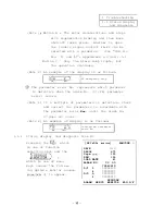
The status display and diagnosis are executed with the
display and switches on the SF-CA card.
When linking
an NC and bus line,
the status display and diagnosis can
be executed on the NC CRT.
1.1.1
Status display and diagnosis from spindle amplifier
For instructions for operating the display and switches,
see Reference
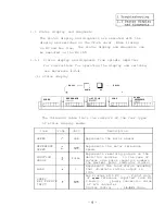
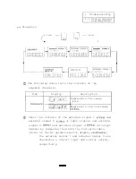
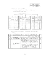
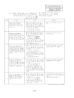
(1) Status display
Shift
q
Shift
D O W N
U P
3
SPEED
REFERENCE
P O
S I T I O N
SPEED
LOAD
REFERENCE
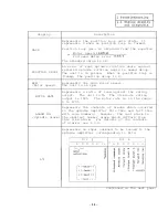
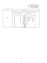
The following table lists the contents of the four types
of status display modes.
Item
Code
SPEED
REFERENCE
SPEED
POSITION
DROOP
LOAD
SPEED
R E F E R E N C E
INPUT
Unit
Description
rpm
Represents the motor speed.
Pulse
%
Represents the motor reference
speed.
Represents remaining pulses on the
deviation counter.
In the case of
reverse side pulse (negative number),
the decimal point indicator lights.
Represents the load status assuming
that 30-minute rating output is
100%.
Bus linkage with NC . . . 2-port data
of
speed
reference inputted from NC
S analog . . .
conversion value
of A/D converter
Digital control . . .
value
Содержание FREQROL-SF
Страница 100: ... 3 Display lamps See Appendix 8 2 4 Check terminals See Appendix g 3 95 ...
Страница 101: ......
Страница 102: ......
Страница 103: ......
Страница 104: ......
Страница 105: ......
Страница 106: ......
Страница 107: ......
Страница 108: ......
Страница 109: ......
Страница 110: ......
Страница 111: ......
Страница 128: ......
Страница 129: ......
Страница 130: ......
Страница 131: ......
Страница 132: ......
Страница 133: ......
Страница 134: ......
Страница 135: ......
Страница 136: ......
Страница 137: ......
Страница 138: ......
Страница 139: ......
Страница 140: ......
Страница 141: ......
Страница 142: ......
Страница 143: ......
Страница 144: ......
Страница 145: ......
Страница 146: ......
Страница 147: ......
Страница 148: ......
Страница 149: ......
Страница 168: ...I J No Common Signal description waveform Example of waveform Orientation stop state 13 5 16 5V 9 1lV 1 300ILsec 163 ...


