


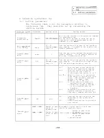
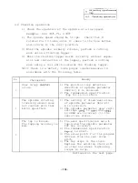


4. Adjusting synchronous tap
4.1 Setting parameters
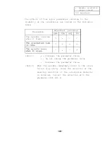
The following table lists the parameters relating to
synchronous tap.
They should be set by referencing the
settting method.
Parameter
Setting value
Setting method
Set the time constant of the position command
Fundamental
for synchronous tap.
specification
Sets the start up time +a when the tap is
rotated up to the maximum speed by the S
command 200
Axis
10 20
Sets the position loop gain in the synchro-
tion,
axis
tag-g
Standard
tapping.
It should be the same as the
ting: 15
spindle parameter PGC.
Spindle
Sets the gear ratio between the spindle and
meter
sgear
0
spindle encoder.
If the spindle encoder is
not used,
0
should be set.
Spindle
meter
PGC
10 20
Sets the position loop gain in the synchro-
Standard
tapping.
It should be the same as tap
ting: 15
g of the axis specification, axis
Spindle
meter
ORS2
bit F . . .
Sets the zero return direction
before the synchronous tapping.
bit E . . .
Sets the rotation direction of
the position loop detector.
In the semi-close state, it is 0.
bit
When it is set to 1, excitation
takes place in the position loop
state.
The response increases
against the impact load.
Normally,
it is set to 0.
bit A . . .
0: Close (when an encoder is
provided with the spindle).
1: Semi-close (when an encoder
is not provided with the
spindle.)
bit 9 . . . Determines the direction of the
spindle rotation for position
loop motor command direction G84.
Spindle
meter
TYP
0001
0000 . . . .
Performs the zero return at the
beginning of the synchronous
tapping.
0001 . . . .
Enters the position loop without
zero return.
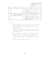
Number of gear The number of gear teeth of each gear
teeth on
should be precisely input.
spindle side
Spindle
number of gear teeth
meter
Number of gear
Motor speed x
of motor
teeth on motor
number of gear teeth
side
of spindle
= spindle speed
Содержание FREQROL-SF
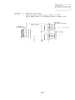
Страница 100: ... 3 Display lamps See Appendix 8 2 4 Check terminals See Appendix g 3 95 ...
Страница 101: ......
Страница 102: ......
Страница 103: ......
Страница 104: ......
Страница 105: ......
Страница 106: ......
Страница 107: ......
Страница 108: ......
Страница 109: ......
Страница 110: ......
Страница 111: ......
Страница 128: ......
Страница 129: ......
Страница 130: ......
Страница 131: ......
Страница 132: ......
Страница 133: ......
Страница 134: ......
Страница 135: ......
Страница 136: ......
Страница 137: ......
Страница 138: ......
Страница 139: ......
Страница 140: ......
Страница 141: ......
Страница 142: ......
Страница 143: ......
Страница 144: ......
Страница 145: ......
Страница 146: ......
Страница 147: ......
Страница 148: ......
Страница 149: ......
Страница 168: ...I J No Common Signal description waveform Example of waveform Orientation stop state 13 5 16 5V 9 1lV 1 300ILsec 163 ...


