-
289
-
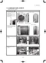
2 Latches on front side
2 more Latches on rear side
Totally 4 Latches
〔
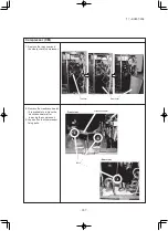
Top view of PCB after removing the cover
〕
〔
Side view after lifting
〕
〔
Top view
〕
〔
Front view
〕
Screws
Screws
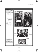
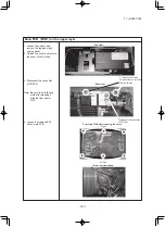
Main PCB (PCB1) on the upper layer
1. Loosen the screws and
remove the top panel and
service panel.
2. Unlatch the cover and remove
the cover of control box.
3. Disconnect the connector
of CNFAN.
Note: Be sure to do following
work after elapsing 3
minutes from power
OFF.
Disconnect the connector
of CNFAN.
4. Loosen 6 screws and lift
up the main PCB.
'17 • SCM-T-225
Содержание SRK60ZSX-S
Страница 52: ... 51 17 SCM T 225 C 2 C 1 C 2 C 1 C 2 C 1 A B G E F D B A PFA004Z025 Model FDE50VG ...
Страница 107: ... 106 17 SCM T 225 source PJA012D783 ...
Страница 349: ... 348 17 SCM T 225 l l l l l l er l l K K 12 5 Superlink E board SC ADNA E ...
Страница 350: ... 349 17 SCM T 225 l l l l l l l l ...


