background image

- 9 -

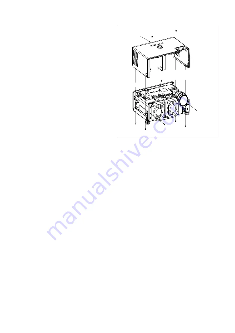
2. Removal of the top cover

1.  Remove the front cover and back cover following “1. 

Removal of the front cover and back cover”.

2.  Remove the four screws (a) as shown in Fig. 2-2.
3.  Remove the two screws (b) as shown in Fig. 2-2.
4.  Place the projector bottom down as shown in Fig. 

2-2.

5.  Remove the two screws (c) as shown in Fig. 2-2.
6.  Lift the top cover in the arrow's direction as shown in 

Fig. 2-2.

(a)

(b)

(c)

Top cover

CN6

Fig. 2-2

Содержание XD206U

Страница 1: ...p 205 W Picture Size 40 300 inch wide aspect ratio rate 4 3 PC compatibility 640 x 400 Expand 800 x 600 Real 1 024 x 768 Compress SD206U 640 x 400 Expand 1 024 x 768 Real 1 280 x 1 0224 Compress XD206U XD206U G Sync on Green available Video compatibility NTSC NTSC 4 43 PAL including PAL M N SECAM PAL 60 Component Video DVD HDTV 480i p 576i p 720p 1080i Speaker 2W Mono Round type ø2 5cm x 1 S Video...

Страница 2: ...ompliant product from non RoHS compliant product G marking With G marking RoHS compliant product Without G marking Non RoHS compliant product Sample 3 Labels of RoHS compliant service parts bear G marking for identification purpose Sample 4 Don t use non RoHS compliant parts with RoHS compliant products 5 Service parts for RoHS compliant products are listed in the parts catalog contained in the se...

Страница 3: ...13 8 Removal of the DIP FIR PCB ASSY 13 9 Removal of KEYPAD PCB ASSY 14 10 Removal of the lens 14 11 Removal of DMD 15 PACKING 16 FILE MAINTENA REPLACING THE LAMP 1 MAINTENANCE 2 ENGINEERING MODE 3 LIFE TIME OF THE CONSUMABLE PARTS 3 INSTALLATION OF DLP COMPOSER TM LITE AND PREPARATIONS 4 DOWNLOAD OF THE FIRMWARE 6 FILE ELCTADJ ELECTRICAL ADJUSTMENT 1 ADC ADJUSTMENT 2 C W DELAY ADJUSTMENT 2 FILE D...

Страница 4: ...5V standby output Replace AC socket Replace AC power cable Replace Fuse Replace keypad and keypad FPC cable Replace POWER PCB ASSY NG Check MAIN PCB ASSY and AC power cable Replace MAIN PCB ASSY Fan failure after turning on Check fan connection OK NG OK NG NG Check fan Check MAIN PCB ASSY Reconnect fan Replace fan Replace MAIN PCB ASSY TROUBLESHOOTING Power source 1 ...

Страница 5: ...LED indicator and follow indicative actions Replace lamp Replace POWER PCB ASSY Replace lamp power unit Replace MAIN PCB ASSY NG Check color wheel rotation while power on Replace optical unit No Volume Check keypad and keypad FPC cable OK NG OK NG NG Check speaker Check MAIN PCB ASSY Replace keypad and keypad FPC cable Replace speaker Replace MAIN PCB ASSY Power source 2 ...

Страница 6: ... cable Check monitor out signal Check optical unit Turn on source Replace cable Replace MAIN PCB ASSY Replace optical unit Video No Signal Check source OK NG OK NG NG Check cable Check optical unit Turn on source Replace cable Replace optical unit Video signal 1 ...

Страница 7: ...CB ASSY Check optical unit Adjust input signal Replace MAIN PCB ASSY Replace optical unit Color abnormal Check input cable and signal setting OK NG OK NG NG Check color wheel Check MAIN PCB ASSY Adjust input signal Adjust color wheel Replace MAIN PCB ASSY OK NG Check optical unit Replace optical unit Video signal 2 ...

Страница 8: ... remote control sensor Check MAIN PCB ASSY Replace remote control NG Replace battery Replace remote control sensor Replace MAIN PCB ASSY Button failure Check keypad and keypad FPC cable OK NG NG Check MAIN PCB ASSY Replace keypad and keypad FPC cable Replace MAIN PCB ASSY Operation function ...

Страница 9: ... Standby Red Solid The projector is powered and ready Lamp failure Green Blinking To replace lamp and reset the lamp hour Fan failure Green Green Solid To check if the fan is clogged with dust or dirt and lean it Lamp life warning Amber Solid The lamp has reached its end of life and must be changed soon The lamp will continue to operate until it fails Power off Green Flashing The projector is shut...

Страница 10: ...x 864 67 50 75 00 1024 x 768 SXGA60b SXGA60 1280 x 960 60 00 60 00 1024 x 768 SXGA60 1280 x 1024 63 98 60 02 960 x 768 MAC13 VGA67 640 x 480 35 00 66 67 800 x 600 1024 x 768 MAC16 SVGA75 832 x 624 49 72 74 55 800 x 600 1024 x 768 MAC19 XGA75 1024 x 768 60 24 75 02 800 x 600 1016 x 768 MAC21 SXGA75 1152 x 870 68 59 74 96 1024 x 768 HP75 XGA75 1024 x 768 62 94 74 92 800 x 600 1024 x 768 SUN66a SXGA6...

Страница 11: ...al generator supplies this signal as a green signal the projector receives it as Y CB CR signal Therefore this signal is projected as a full white SMPTE signal Timing of SVGA signal Vertical frequency 60 Hz DOT CLOCK MHz 40 0 VP H 628 HP DOT 1056 VDISP H 600 HDISP DOT 800 VDW H 4 HDW DOT 128 VBP H 23 HBP DOT 88 Interlace Signal polarity HD VD Timing of XGA signal Vertical frequency 60 Hz DOT CLOCK...

Страница 12: ...s replaced Perform at least 4 hour aging after the completion of this adjustment Necessary files The following file is necessary to run the program SVGA_WRGB_64scale file in DLP Composer TM Lite folder for SD206U XGA_WRGB_64scale file in DLP Composer TM Lite folder for XD206U XD206U G Adjustment procedure 1 Connect the projector and the PC using the VGA cable 2 Connect the power cord to the projec...

Страница 13: ...istics These characteristics are often not evident from visual inspection nor can the protection afforded by them necessarily be obtained by using replacement compo nents rated for higher voltage etc Replacement parts which have these special safety characteristics are identified in this ser vice manual Electrical components having such features are identified by shading on the schematic diagram a...

Страница 14: ...ning 1 Operation of this projector outside the cabinet or with the cover removed presents a shock hazard from the projector power supplies 2 When a short circuit has occurred replace those components that indicate evidence of overheating 3 Grounding circuit continuity is vital for safe operation of equipment Do not remove ground connection while the power cord is still connected to the supply Disc...

Страница 15: ...a limited marking space on the board Solder may be indicated as S Joints as J and PCA as P Circuit boards using lead free solder and those using eutectic solder may be used together in the same product Instructions for resoldering For circuit boards using lead free solder use lead free solder For circuit boards using eutectic solder use eutectic solder Separate the soldering iron for lead free sol...

Страница 16: ... 4 EXPOSED VIEW DLP ASSY 3 4 10 12 5 2 9 11 8 12 1 7 6 Fig 1 1 ...

Страница 17: ...e 1 FRONT COVER 2 BACK COVER 3 TOP COVER 4 MAIN PCB ASSY 5 MOTOR FAN EXHAUST 6 CABLE 7 POWER PCB ASSY 8 SOCKET AC WIRE 9 SPEAKER 10 LAMP COVER 11 DIP FIR PCB ASSY 12 FAST FOOT Table 1 1 Parts list See page 2 of PARTS LIST ...

Страница 18: ... 6 Sub ASSY 1 2 3 4 Item No Part name 1 LAMP POWER UNIT 2 KEYPAD PCB ASSY 3 KEY PRINTED COVER 4 RING CAP Fig 1 2 Table 1 2 Parts list See page 2 of PARTS LIST ...

Страница 19: ...0 2 7 Item No Part name 1 SENSOR CW PCB ASSY 2 LIGHT PIPE 3 COLOR WHEEL 4 MOTOR FAN LAMP 5 DMD SOCKET 6 DMD CHIP 7 DMD PCB ASSY 8 LENS UNIT 9 LAMP CASE except NSH LAMP 10 NSH LAMP Parts list See page 3 of PARTS LIST Fig 1 3 Table 1 3 ...

Страница 20: ... 2 1 1 2 Remove the six screws b as shown in Fig 2 1 1 3 Place the projector upside down as shown in Fig 2 1 2 4 Remove the six screws a as shown in Fig 2 1 2 5 Remove the front cover as shown in Fig 2 1 2 6 Remove the back cover as shown in Fig 2 1 2 a a b Fig 2 1 1 a Back cover Front cover Fig 2 1 2 ...

Страница 21: ...over and back cover 2 Remove the four screws a as shown in Fig 2 2 3 Remove the two screws b as shown in Fig 2 2 4 Place the projector bottom down as shown in Fig 2 2 5 Remove the two screws c as shown in Fig 2 2 6 Lift the top cover in the arrow s direction as shown in Fig 2 2 a b c Top cover CN6 Fig 2 2 ...

Страница 22: ...n in Fig 2 3 1 4 Disconnect the four connectors SP BALLAST STBY CTRL and POWER as shown in Fig 2 3 1 5 Remove the four screws a as shown in Fig 2 3 2 6 Remove the screw b and sheet metal c as shown in Fig 2 3 2 7 Remove the MAIN PCB ASSY as shown in Fig 2 3 2 8 Remove the four screws a as shown in Fig 2 3 3 9 Remove the motor fan exhaust as shown in Fig 2 3 3 FAN2 FAN3 IRI CW FAN1 CW SEN THER SP S...

Страница 23: ...r fan exhaust 4 Remove the four screws a as shown in Fig 2 4 1 5 Remove the two screws b as shown in Fig 2 4 1 6 Lift the ballast board as shown in Fig 2 4 1 7 Disconnect the two connectors lamp connector and PJ2 as shown in Fig 2 4 1 8 Remove the one screw a as shown in Fig 2 4 2 9 Release the four rivet b as shown in Fig 2 4 2 10 Remove the lamp power unit as shown in Fig 2 4 2 a a a b Ballast b...

Страница 24: ...move the optical unit as shown in Fig 2 5 a Fig 2 5 6 Removal of the POWER PCB ASSY 1 Remove the front cover and back cover following 1 Removal of the front cover and back cover 2 Remove the top cover following 2 Removal of the top cover 3 Remove the MAIN PCB ASSY following 3 Removal of the MAIN PCB ASSY and motor fan exhaust 4 Remove the ballast board following 4 Removal of the lamp power unit 5 ...

Страница 25: ...CB ASSY 1 Remove the front cover and back cover following 1 Removal of the front cover and back cover 2 Remove the top cover following 2 Removal of the top cover 3 Remove the MAIN PCB ASSY following 3 Removal of the MAIN PCB ASSY and motor fan exhaust 4 Remove the ballast board following 4 Removal of the lamp power unit 5 Remove the optical unit following 5 Removal of the optical unit 6 Remove the...

Страница 26: ...as shown in Fig 2 9 a Ring cap KEYPAD PCB ASSY Key printed cover Fig 2 9 10 Removal of the lens 1 Remove the front cover and back cover following 1 Removal of the front cover and back cover 2 Remove the top cover following 2 Removal of the top cover 3 Remove the MAIN PCB ASSY following 3 Removal of the MAIN PCB ASSY and motor fan exhaust 4 Remove the ballast board following 4 Removal of the lamp p...

Страница 27: ...st board following 4 Removal of the lamp power unit 5 Remove the optical unit following 5 Removal of the optical unit 6 Remove the four screws a as shown in Fig 2 11 1 7 Remove the DMD chip and DMD PCB ASSY as shown in Fig 2 11 1 Note If you do not have fixture you also can point the lens against the table and then remove the 4 screws See Fig 2 11 2 Note After remove the 4 screws you can see the D...

Страница 28: ...t name Item No Part name 1 SOFT CASE 7 LENS COVER 2 INSTRUCTION CD 8 PE BAG 3 SAFETY MANUAL 9 PACKING CUSHION RIGHT 4 REMOTE CONTROL 10 PACKING CUSHION LEFT 5 COMPOSITE VIDEO CABLE 11 PACKING CASE 6 AC POWER CORD Parts list See page 4 of PARTS LIST ...

Страница 29: ...d out quickly the lamp may break scattering glass fragments Do not spill liquid on the removed lamp box or do not place it near any flammable object or where children can reach to prevent injury or fire 6 Load a new lamp box securely into the projector in the right orientation 7 Put the handle back to the original posi tion Make sure that the handle is locked 8 Tighten up the screws c using a Phil...

Страница 30: ...an the projector and the ventilation grilles When the grilles become dirty wipe them with a soft cloth dampened with diluted mild detergent and then wipe them with a dry cloth To protect the surface of the projector from fading or deteriorating Do not spray insecticide on or inside the projector Do not use benzine or thinner to clean it Do not let rubber or plastic materials contact with projector...

Страница 31: ...tem respectively Step 4 So we know that this device has ever happened color wheel and lamp failure from the last reset all setting But we don t know which events happen first Shipment Reset Let all parameters go back to default This reset is much more powerful than the factory reset un der the end user interface FAN1 Control the outer fan on the front cover Keep the default value Don t change it F...

Страница 32: ...brary_35 folder Installing DLP Composer TM Lite 1 Double click DLP Composer Lite v3 6 Setup exe 2 Installation starts Click Next to continue the installation process 3 On the License Agreement screen move the scroll bar on the right to the bottom select I accept and agree to be bound by all the terms and conditions of this License Agreement and click Next to continue the installation process 4 On ...

Страница 33: ...poser TM Lite from the Start menu and select the icon named Install DDP2000 USB Driver The USB support is installed When Hit any key to continue is displayed on the screen press any key on the keyboard and wait for the installation process to complete Preparation 1 Start DLP Composer TM Lite The dialog shown below appears 2 Select Preferences from the Edit menu The DLP Composer Preferences dialog ...

Страница 34: ...ton of Flash Image File of Options Select firmware to download from among XD206_Flash_v img and SD206_Flash_v img 10 Put a checkmark to Skip Boot Loader Area 11 Plug the power code of the projector into the wall outlet 12 Press the MENU ENTER and POWER buttons of the projector simultaneously to enter the download mode When the projector enters the download mode the POW ER LED and STATUS LED light ...

Страница 35: ...Model number serial number 2 Part number and its description 3 Quantity Unless all the required information is supplied the delivery of your order may be delayed Critical components MARK B C D F G J K TOLERANCE 0 1 0 25 0 5 1 2 5 10 MARK M N V X Z P Q TOLERANCE 20 30 10 40 20 80 20 100 0 30 10 MARK B C D F G TOLERANCE pF 0 1 0 25 0 5 1 2 ...

Страница 36: ...VER SD206U 3 750D033O60 TOP COVER XD206U 3 750D044O30 TOP COVER XD206U G 4 935D949O70 MAIN PCB ASSY SD206U 4 935D935O50 MAIN PCB ASSY XD206U XD206U G 5 288P283O10 MOTOR FAN EXHAUST 6 246D049O20 CABLE 7 935D935O60 POWER PCB ASSY 8 246D041O10 SOCKET AC WIRE 9 480D039O10 SPEAKER 10 750D036O50 LAMP COVER 11 935D935O70 DIP FIR PCB ASSY SD206U 11 935D949O50 DIP FIR PCB ASSY XD206U XD206U G 12 771D134O10...

Страница 37: ...ART NAME DESCRIPTION EXPOSED VIEW Optical unit Fig 1 3 1 935D949O30 SENSOR CW PCB ASSY 2 499D112O20 LIGHT PIPE 3 499P050O10 COLOR WHEEL 4 288P298O10 MOTOR FAN LAMP 5 499D112O30 DMD SOCKET SD206U 5 499D112O10 DMD SOCKET XD206U XD206U G 6 276P255O10 DMD CHIP 7 935D949O10 DMD PCB ASSY 8 499D116O30 LENS UNIT SD206U 8 499D116O10 LENS UNIT XD206U XD206U G 9 499D116O20 LAMP CASE except NSH LAMP 10 253P20...

Страница 38: ...71D515O10 INSTRUCTION CD XD206U G 3 871D501O10 SAFETY MANUAL SD206U 3 871D495O60 SAFETY MANUAL XD206U 3 871D510O90 SAFETY MANUAL XD206U G 4 939D294O10 REMOTE CONTROL 5 246D040O20 COMPOSITE VIDEO CABLE 6 246C359O10 AC POWER CORD UK SD206U XD206U 6 246C383O20 AC POWER CORD EUROPE SD206U XD206U 6 246C483O10 AC POWER CORD US 7 702D285O10 LENS COVER 8 772D045O10 PE BAG 9 803D351O10 PACKING CUSHION RIGH...

Страница 39: ...50D044O30 TOP COVER XD206U G 750D036O40 BACK COVER 750D036O50 LAMP COVER 771D134O10 FAST FOOT PACKING PARTS AND ACCESSORY 1 772D045O20 CASE SOFT SOFT CASE 2 871D501O20 INSTRUCTION CD SD206U 2 871D495O50 INSTRUCTION CD XD206U 2 871D515O10 INSTRUCTION CD XD206U G 3 871D501O10 INSTRUCTION BOOK SAFETYMANUAL SD206U 3 871D495O60 INSTRUCTION BOOK SAFETYMANUAL XD206U 3 871D510O90 INSTRUCTION BOOK SAFETYMA...

Страница 40: ...1A Insulation voltage minimum 5000 Vac PC106 Photo coupler Nec Electronics Corp Compound Semiconductor Device Div PS2561 PS2561A Insulation voltage minimum 5000 Vac PC107 Photo coupler Nec Electronics Corp Compound Semiconductor Device Div PS2561 PS2561A Insulation voltage minimum 5000 Vac PC200 Optical Isolator Lite On Technology Corp LTV 357T Minimum isolation voltage 3750Vac PC300 Optical Isola...

Страница 41: ...DI IRQZ EXT_ARSTZ 64 U27 TL5001A U21 CLK gen CDCR83 FRONT IR CN2 3pin SH 4pin FPC J10 CWCTR CWY1 CWY2 CWY3 3 4 BINSEL 1 0 2 J12 R OUT G OUT B OUT HD OUT VD OUT 8 P2_CLK P2_FIELD P2_Y 7 0 P2_UV 7 0 8 U47 DECODER TVP5147M1 U28 Regulater AIC1117 3 3 U35 Regulater AIC1117 1 8 5V Y1 OSC 50 000MHz CS0 CS3 PMBLS 1 0 SDRAM_CLK CKE RAS CAS DQM 1 0 POWER STBYON JP8 POSENSE SYSRSTZ U30 POWER MONITOR TPS3307 ...

Отзывы: