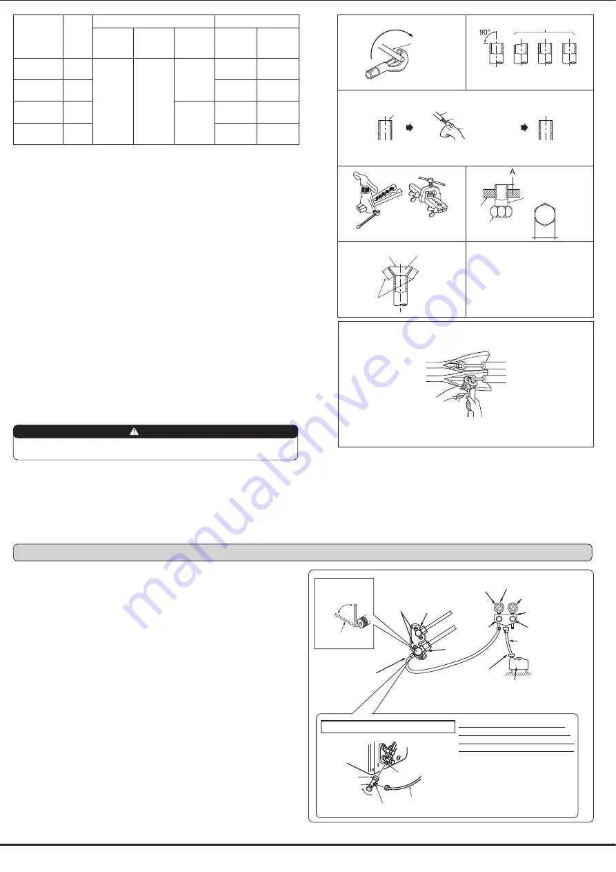
3-2. FLARE CONNECTION
1) Cut the copper pipe as straight as possible with a pipe cutter. (Fig. 1, 2)
2) Remove all burrs from the cut section of the pipe, ensuring that precautions are taken to
avoid getting metal shavings into the piping. (Fig. 3)
Y$Z"M\ O&"&&
4) Flaring work (Fig. 4, 5). Firmly hold copper pipe in the dimension shown in the table. Select
A inch (mm) from the table according to the tool you use.
5) Check
^"& \ %
QN\ NMONN & &
3-3. PIPE CONNECTION
% \ _ & ; ;M
`N O\ " +M +; N
z & &&{ ; &&" +
in burns or frostbite.
Indoor unit connection
Connect both liquid and gas piping to indoor unit.
&&+ NN |$\ N&&{ &&+-
frigeration oil on screw threads. Excessive tightening torque will result in damage on the
screw.
@O OYN\
}_ ; ;M N~O
=M " \
Outdoor unit connection
Connect pipes to stop valve pipe joint of the outdoor unit following the same procedure
detailed in Indoor unit connection.
%O _&
3-4. INSULATION AND TAPING
1) Cover piping joints with pipe cover.
2) For outdoor unit side, insulate the piping, including valves.
3) Apply piping tape (G) starting from the connection on the outdoor unit.
`&& ; O"&
"+ O && &M -
tion.
Copper
pipe
Good
Tilted
No good
Fig. 1
Fig. 2
Burr
Copper pipe
Spare reamer
Pipe cutter
Fig. 4
Fig. 3
Smooth all around
Even length
all around
Inside is shin-
ing without any
scratches.
Fig. 5
Fig. 6
Flare nut
Die
Copper pipe
Clutch type
Flaring tool
Wing nut type
Pipe diameter
inch (mm)
B
inch
(mm)
A inch (mm)
Tightening torque
Clutch
type tool
for R410A
Clutch
type tool
for R22
Wing nut
type tool
for R22
ft-lb
N"$
"
ø 1/4 (6.35)
21/32
(17)
0 to 0.02
(0 to 0.5)
0.04 to 0.06
(1.0 to 1.5)
0.06 to 0.08
(1.5 to 2.0)
10 to 13
(140 to 180)
13.7 to 17.7
ø 3/8 (9.52)
7/8 (22)
25 to 30
(350 to 420)
34.3 to 41.2
ø 1/2 (12.7)
1-1/32
(26)
0.08 to 0.10
(2.0 to 2.5)
36 to 42
(500 to 575)
49.0 to 56.4
ø 5/8 (15.88)
1-5/32
(29)
54 to 58
(750 to 800)
73.5 to 78.4
4-1. PURGING PROCEDURES AND LEAK TEST
1) Remove service port caps from stop valves on both sides of refrigerant lines. (The stop
valves are fully closed when shipped.) Leave closed.
2) Connect gauge manifold to ports of stop valves.
3) Evacuate the system to 4000 microns from both service valves. System manifold gauges
must not be used to measure vacuum. A micron gauge must be used at all times. Break
the vacuum with Nitrogen(N2) into the discharge service valve to 0 PSIG.
4) Evacuate the system to 1500 microns. Break the vacuum with Nitrogen(N2) into the
discharge service valve to 0 PSIG.
5) Evacuate the system to 500 microns.
6) Close gauge manifold valves, stop the pump, and conduct a 30 minute rise test.
7) System should hold 500 microns for a minimum of 1 hour.
8) Fully open all stop valves on both sides of gas pipe and liquid pipe. Operating without
fully opening lowers the performance and this causes trouble.
9) Refer to 1-3 and charge the prescribed amount of additional refrigerant if needed. Be
sure to charge slowly with liquid refrigerant. Otherwise composition of the refrigerant in
the system may be changed and affect performance of the air conditioner.
10) Remove gauge manifolds and replace service port caps and tighten.
11) Leak test
Uneven Burred
WARNING
When installing the unit, securely connect the refrigerant pipes before starting the
compressor.
B
Stop valve for
GAS
Stop valve cap
(Torque 15 to
22 ft-lb, 19.6 to
?"O?!!
Y!!N"$
Vacuum pump (or the vacuum
pump with the function to
&M; \$
Gauge manifold valve
(for R410A)
Compound pressure gauge
(for R410A)
–14.7 psi [Gauge]
!!& $
Handle
Low
Handle High
Adapter for
preventing the
; \
Charge hose
(for R410A)
*Close
*Open
Hexagonal wrench
Precautions when using the control valve
When attaching the control valve
to the service port, valve core may
deform or loosen if excess pressure
is applied. This may cause gas leak.
Service port
Charge hose
Body
Close
Open
Control valve
A
When attaching the control valve to
the service port, make sure that the
valve core is in closed position, and
then tighten part A. Do not tighten
part A or turn the body when valve
core is in open position.
Service port cap
(Torque 10 to 13 ft-Ib,
Y"O140
to 180 kgfcm)
*4 to 5 turns
Stop valve for LIQUID
Pressure gauge
(for R410A)
4. PURGING PROCEDURES, LEAK TEST, AND TEST RUN


