background image

Model   JT-SB216ESH-DG-CE

No.

 Parts No.   Name of part

Critical Remarks

  Price

for safety

1.

Y45 612 801 Panel(back)

1

2.

X45 608 809 Decoration plate

1

3.

Y45 612 810 Decoration plate

1

Power

4.

M45 664 833 Board fix plate (back)

1

5.

H00 163 007 PTT screw 4×16

35

6.

M45 664 173 Circuit board

1

JT-24S-B

7.

M45 664 857 Packing

1

3000㎜

8.

M45 664 801 Sensor holder

1

9.

Y45 612 807 Side panel(left)

1

10.

Y45 612 371 Wiring diagram

1

11.

Y45 621 800 Front panel

1

12.

M45 632 045 Special screw 4×16

4

13.

M45 664 823 Panel holder (left)

1

14.

M45 664 824 Panel holder (right)

1

15.

M45 664 820 Exhaust duct

1

16.

Y45 612 808 Side plate(right)

1

17.

Y45 612 802 Panel(front)

1

18.

M45 664 828 Board fix plate (front)

1

19.

M45 664 174 Circuit board

1

JT-24S-C

20.

Y45 612 806 Panel(under)

1

  Q'ty
pcs/unit

47

Содержание JT-SB216ESH-DG-CE

Страница 1: ...BOOK Model JT SB216ESH W CE JT SB216ESH DG CE FOR DEALERS Nameplate February 2010 No U131 B Repair work should be performed by the manufacturer its service agent or similarly qualified person in order to avoid hazards ...

Страница 2: ...5 Specifications 8 6 Outside dimensions 8 7 Electrical wiring diagram 9 8 Basic circuit diagram 10 16 9 Principles of operation 17 18 10 Troubleshooting 19 23 11 How to call 24 12 Service inspection list 24 13 Disassembly and assembly 25 33 14 Parts catalog 34 58 JT SB216ESH W CE 35 46 JT SB216ESH DG CE 47 58 ...

Страница 3: ...e wait for at least 90 seconds before disassembling the product Not turning off the power may cause electric shock Use proper parts and tools Use the parts listed in the service parts list of the sub ject model with appropriate tools when repairing Using improper parts and tools may cause electric shock fire and or injury Check insulation Upon completing repair work always measure the insulation r...

Страница 4: ...ot require a paper or cloth towel thus eliminating the dumping paper waste and the exchanging of towels Also the hand dryer is easy to clean 8 Highly safe with mischievous use prevention timer To prevent continuous operations of the hand dryer by mischievous use or malfunction it has a built in timer that automatically stops drying upon reaching a specific period of time OUpon completing repair wo...

Страница 5: ... when drying hands A Hot air temperature control function Hot air temperature is constantly at 35 C regardless of the room temperature Room temperature 10 35 C B Optional function The hand dryer may be installed on the floor using the optional special stand JP S15FS H E 3 Improved points Item Old Model JT SB216DS Round hole nozzle 65 650 4 11 JP S26FS H E Nozzle Noise dB Rated power consumption W ...

Страница 6: ...ure indicate antimicrobial material Drain tank Unit Heater Drain hose Hand drying area Check lamp Power lamp Display Emblem Heater lamp Black wall area Sensor Illumination lamp Sensor Air filter OFF ON O I O I OFF ON Power Air speed Heater 4 Names and functions of components 4 1 Structure and appearance ...

Страница 7: ...on or flashing turn off the power shut off the ground fault circuit interrupter and When not using the unit for long periods of time With the heater switch OFF When the heater switch is turned ON approx 1100 W of power is consumed to accumulate heat by operating the heater Turn the power switch off The unit consumes approximately 2W of power even if unused when the power is on With both hands open...

Страница 8: ...ng 650 Rated Current A 4 6 5 During heat accumulation During hand drying 4 0 Weight kg 14 Drain Tank R Noise dB Terminal block location Terminal block location Heater switch Switch door Wind volume knob Power switch Drain tank Air filter Power cord hole On the back Mounting plate dimensions Unit mm 5 Specifications 6 Outside dimensions JT SB216ESH W CE JT SB216ESH DG CE ...

Страница 9: ... 9 JT SB216ESH W CE JT SB216ESH DG CE 7 Electrical wiring diagram ...

Страница 10: ...eater ON AC220V AC230V AC240V JT 24M Between TAB3 TAB4 0V JT 24M CN7 5P 15V JT 24M CN7 1P 5V JT 24M CN6 1P Clock frequency 8MHz JT 24M IC2 14P Reset input 5V JT 24M IC2 11P Reset input 5V JT 24M IC1 11P Clock frequency 8MHz JT 24M IC1 14P Carrier frequency 13 9kHz JT 24M IC1 3P 8 Basic circuit diagram 8 1 Circuit diagram and check points 1 Main circuit JT 24M ...

Страница 11: ... 12 2 Sub circuit JT 24S ...

Страница 12: ...nal waveform JT 24M CN7 2P JT 24S B CN14 2P Lower sensor s light emitting signal waveform JT 24M CN5 2P JT 24S C CN15 2P 100msec Rises when hands are inserted Does not appear when hands are inserted Influence of light emission by the lower sensor 100msec 100msec Room thermostat characteristics JT 24M CN4 2P Heater thermostat characteristics JT 24M CN9 2P FIN overheat detector characteristics JT 24...

Страница 13: ...ly voltage AC220V AC230V AC240V JT 24M Between TAB1 TAB2 Heater power supply With heater ON AC220V AC230V AC240V JT 24M Between TAB3 TAB4 5V JT 24M CN6 1P 0V JT 24M CN7 5P 15V JT 24M CN7 1P 8 2 Circuit board diagram and check points 1 Main circuit board Control circuit board ...

Страница 14: ...jumper wire JA is cut off the illumination lamp turns off 3 Wind volume circuit board 4 Light receiving circuit board 5 Light emitting circuit board 6 Illumination circuit board Blue LED 2 Indicator circuit board ...

Страница 15: ...14 2P Does not appear when hands are inserted Influence of light emission by the lower sensor 100msec 100msec Room thermostat characteristics JT 24M CN4 2P Heater thermostat characteristics JT 24M CN9 2P FIN overheat detector characteristics JT 24M IC1 8P Resistance CN4 2P Voltage Temperature 150 C 29 84kΩ 3 74V 200 C 8 00kΩ 2 22V 250 C 2 72kΩ 1 07V Resistance CN9 2P Voltage Temperature 25 C 330 o...

Страница 16: ... error display persists till the voltage retained in the circuitry is discharged till the microcomputer is reset 2 Hand detection and operation 1 Hand detection sensor is an infrared sensor assembled with the light emitting sensor infrared emitting diode light receiving sensor photo diode etc and consists of the upper this side sensor and the lower inner sensor 2 Reflection type upper sensor The s...

Страница 17: ... thermostat detection temperature is 35 C or higher 5 Extinguishing of the illumination lamp 1 If the jumper wire JA on the indicator circuit board JT 24S A is cut off the illumination lamp extinguishes 2 Before cutting off the jumper wire make sure to turn the power switch OFF and wait for 40 seconds minimum 6 Test mode Error display mode 1 Content Display the latest error occurred When no error ...

Страница 18: ...or 0 4 seconds OFF for 0 4 seconds O OFF Quick flicker ON for 0 1 second OFF for 0 1 second Troubles with error display Power Heater Check Blue LED Switch Power ON 0Ω Switch Power OFF Ω 10 Troubleshooting Q Work precautions Before starting the service try to reproduce the malfunction two or three times When servicing always take care to keep proper footing Before starting the service always unplug...

Страница 19: ...may be blown and ZNR1 may be destroyed No display No Operation Power O Heater O Check O Blue LED O Normal value 0Ω Abnormal value Ω side Tester side Blue Blue Red Black White 1Check if the relay connector of motor thermal fuse is disconnected In the terminal block box 2Check if TAB5 and TAB6 connectors are disconnected 3To see if the motor thermal fuse is blown measure the resistance between motor...

Страница 20: ... circuit board for disconnection or displaced mounting position Visually check for cracks on the circuit board corroded electronic parts defective soldering etc Dirty window may shield incoming light Make clean the sensor window Check if the lead wire of the light emitting circuit board CN5 or CN15 is disconnected CN15 is on the light emitting circuit board Check the light emitting circuit board f...

Страница 21: ...cted Disconnected heater thermostat lead wire Disconnecting CN9 from the control circuit board measure the resistance between pins 2 and 3 at the lead wire side If the normal value is not detected replace the thermo lead wire Note If the circuit is open due to broken wires etc the resistance becomes Ω Defective heater thermostat Room thermostat error Power O Heater O Check O Blue LED O Heater erro...

Страница 22: ... is on the indicator circuit board and CN17 on the volume circuit board Disconnected wind volume lead wire Disconnecting CN3 from the control circuit check if the resistance between pins 1 and 2 at the lead wire side changes within the following range when the wind volume knob is turned Unless the normal value is detected replace the volume knob Operation continues after pulling hands out Normal V...

Страница 23: ...n Water leaks from the product 1Check if the drain tank is filled up Drain water Since the main unit may absorb moisture if the product is operate while the drain tank is full drain water will flow over when it is filled up beyond its capacity 2Is the drain tank installed properly Wind does not blow immediately after turning on the power switch and inserting hands It takes 1 second after turning o...

Страница 24: ...w the instructions described in the troubleshooting When servicing always take care to keep proper footing Before starting the service always unplug the power cord from the outlet or turn off the earth leakage breaker when no power cord plug is provided Sufficient care must be taken to avoid electric shock or injury Make sure to connect the power supply wires correctly After completing repairs che...

Страница 25: ...ircuit board clamping nut Indicated by O Assembly precaution Install the volume knob in alignment with the shaft 3 Indicator circuit board and illumination circuit board 1 Remove the maintenance cover See 2 1 2 Disconnect the lead wires and remove the indicator circuit board and the illumination circuit board from the spacers Indicated by O ...

Страница 26: ...nect the lead wires from the control circuit board and remove the cord bushes Indicated by O Assembly precautions Remove the terminal cover before removing the control circuit board Be sure to use the lock washers when installing the grounding wires Assembly precautions Connect the lead wires referring to the printing on the control circuit board Use the cord bushes with the smaller hole diameter ...

Страница 27: ...icated by Q 6 Remove the line filter Indicated by Assembly precautions Set the blower lead wires at the left side of the blower assembly See photograph Replace the packing used in the disassembled section with a new one Take care not to twist the packing when installing it 6 Light emitting circuit board 1 Remove the front panel See 4 1 2 Remove the panel holder left clamping screws Four PTT screws...

Страница 28: ...disassembled section with a new one Take care not to twist the packing when replacing it Assembly precaution Hook the lead wires on the claw on the panel front Indicated by O Assembly precaution Take care not to pinch the lead wires with the board fix plate 5 Remove the board fix plate front Indicated by O Assembly precaution Secure the light emitting circuit board firmly with the claws 6 Remove t...

Страница 29: ...ng it Take care to install the O ring and packing securely Assembly precaution Closely fit the panel under and the panel back together indicated by O before clamping with the screws Assembly precaution Confirm that there are no cracks on the panel under Indicated by O 4 Remove the clamping screws from the back Eight special screws 4 x 16 indicated by O 5 Remove the panel under Assembly precautions...

Страница 30: ...rom the board fix plate back Release the board from the claws at four places indicated by O O Assembly precautions When setting the light receiving circuit board on the board fix plate back confirm the correct mounting direction of the board See photograph After installing the circuit board confirm that the LEDs are not tilting Assembly precaution Run the lead wires within the groove on the side o...

Страница 31: ...ing 4 Remove the grounding wire clamping screw One special PP screw with the spring washer 4 x 8 indicated by O 5 Remove the back cover clamping screws Five special screws 4 x 12 indicated by 6 Remove the heater box Indicated by O 7 Remove the heater box clamping screw One special screw 4 x 8 indicated by O Assembly precautions Hook the claw of the heater box on the square hole in the heater base ...

Страница 32: ...ater thermostat 9 Remove the thermistor heater thermostat clamping screw One special PPT screw 4 x 8 indicated by O 0 Remove the fuse fix plate clamping screw One SW PW PP screw 4 x 8 indicated by O A Remove the thermal fuse fixing screws Two SW PW PP screws 4 x 8 indicated by O Assembly precaution Set the cord clip at the marked position on the thermal fuse lead wire and then clamp it with the sc...

Страница 33: ... PP screw PPT screw PCT screw PTT screw PT screw SET screw SQ SET screw P SET screw PMT screw HS SET screw P R W screw P C W screw P R C W screw R W screw PW PP screw SW PW PP screw Description Cross recess flat head machine screw Cross recess oval head machine screw Cross recess pan head machine screw Cross recess pan head screw with spring washer Cross recess tapping screw Cross recess flat head...

Страница 34: ...64 857 Packing 1 3000 8 M45 664 801 Sensor holder 1 9 M45 664 830 Side panel left 1 10 Y45 612 368 Wiring diagram 1 11 M45 664 800 Front panel 1 12 M45 632 045 Special screw 4 16 4 13 M45 664 823 Panel holder left 1 14 M45 664 824 Panel holder right 1 15 M45 664 820 Exhaust duct 1 16 M45 664 831 Side panel right 1 17 M45 664 829 Duct piece 1 18 M45 664 818 Panel front 1 19 M45 664 828 Board fix pl...

Страница 35: ...9 10 11 12 13 14 15 16 17 18 19 20 21 1 2 3 4 5 6 7 8 36 5 5 5 5 7 7 JT SB216ESH W CE ...

Страница 36: ...e 1 41 M45 664 175 Circuit board 1 JT 24S D 42 M45 664 258 Switch heater 1 43 D41 233 018 Special screw 4 16 9 44 M45 664 176 Circuit board 1 JT 24S E 45 M35 139 095 Spacer 3 46 M45 664 807 Maintenance cover 1 47 M45 664 172 Circuit board 1 JT 24S A 48 M45 664 802 Installation panel 1 49 X40 256 228 Cord band 2 50 M45 664 813 Drain tank 1 51 M45 664 814 Tank cover 1 52 M45 632 047 Special screw 4x...

Страница 37: ...50 51 52 53 54 55 56 57 31 32 33 34 35 36 37 38 39 40 41 42 43 44 45 46 47 48 49 38 52 52 52 5 JT SB216ESH W CE ...

Страница 38: ... M45 632 225 Cord bush 1 66 Y45 606 180 Line filter 1 ESD R 25D B 67 M45 664 815 Drain pipe 1 68 M45 664 803 Air supply duct 1 69 M45 632 046 Special screw 4 50 1 70 M45 664 858 Packing 1 1200 71 M45 664 819 Exhaust duct 1 72 M45 632 229 O ring 1 73 M45 608 227 Blower stopper 1 74 M45 664 811 Blower case 1 75 Y45 611 400 Blower assy 1 76 M45 664 227 Floating rubber 1 77 D41 023 223 Cord clip 2 pcs...

Страница 39: ...70 40 61 62 63 64 65 66 67 68 69 70 71 72 73 74 75 76 77 5 5 5 5 52 5 63 70 70 64 64 63 JT SB216ESH W CE ...

Страница 40: ...l block 1 ML 20 A37 3P 95 H00 154 005 PPT screw 4 12 2 96 M45 664 816 Box reactor 1 97 M34 981 225 Cord bush 1 98 Y45 611 179 Reactor 1 99 H00 312 007 PTT screw 4 6 3 100 M45 664 817 ACL cover 1 101 Y45 611 223 Cord clip 1 102 M45 664 825 Board cover 1 103 M45 664 826 Cover 1 104 M45 667 225 Cord bush 1 105 M45 632 228 Cord bush 1 106 Y45 611 171 Circuit board 1 JT 24M3H Q ty pcs unit 41 ...

Страница 41: ...101 102 103 104 105 106 91 92 93 94 95 96 97 98 99 100 42 49 93 5 77 5 99 JT SB216ESH W CE ...

Страница 42: ... 228 Cord clip 1 119 M45 664 842 Fuse fix plate 1 120 Y45 611 801 Heater 1 121 M45 664 045 Special screw 4 8 1 122 M45 664 841 Heater base right 1 123 M45 640 226 Cord bush 1 124 M45 664 840 Heater base left 1 125 M34 660 019 Special screw 4 8 4 126 Y45 621 226 Cord clip 1 127 M34 869 018 Special screw 4 12 5 128 D40 038 344 Cord clip 1 129 M45 664 838 Back cover 1 130 H00 000 430 PP screw 4 8 1 1...

Страница 43: ...12 44 111 112 113 114 115 116 117 118 119 120 121 122 123 124 125 126 127 128 129 130 131 132 133 shows accessory parts 1 piece 5 1 piece 117 125 125 127 93 JT SB216ESH W CE ...

Страница 44: ... Remarks Price for safety 141 M45 664 225 Lead wire 1 Volume Display 142 M45 664 219 Lead wire 1 Main Display 143 M45 664 221 Lead wire 1 Main Light Receiving 144 M45 664 220 Lead wire 1 Main Light Emitting 145 Y45 611 800 Thermo lead wire 1 45 Q ty pcs unit ...

Страница 45: ... 46 141 142 143 144 145 JT SB216ESH W CE ...

Страница 46: ...T 24S B 7 M45 664 857 Packing 1 3000 8 M45 664 801 Sensor holder 1 9 Y45 612 807 Side panel left 1 10 Y45 612 371 Wiring diagram 1 11 Y45 621 800 Front panel 1 12 M45 632 045 Special screw 4 16 4 13 M45 664 823 Panel holder left 1 14 M45 664 824 Panel holder right 1 15 M45 664 820 Exhaust duct 1 16 Y45 612 808 Side plate right 1 17 Y45 612 802 Panel front 1 18 M45 664 828 Board fix plate front 1 1...

Страница 47: ...9 10 11 12 13 14 15 16 17 18 19 20 1 2 3 4 5 6 7 8 48 5 5 5 5 7 7 JT SB216ESH DG CE ...

Страница 48: ...se 1 41 M45 664 175 Circuit board 1 JT 24S D 42 M45 664 258 Switch heater 1 43 D41 233 018 Special screw 4 16 9 44 M45 664 176 Circuit board 1 JT 24S E 45 M35 139 095 Spacer 3 46 M45 664 807 Maintenance cover 1 47 M45 664 172 Circuit board 1 JT 24S A 48 M45 664 802 Installation panel 1 49 X40 256 228 Cord band 2 50 Y45 612 800 Drain tank 1 51 M45 664 814 Tank cover 1 52 M45 632 047 Special screw 4...

Страница 49: ...50 51 52 53 54 55 56 57 31 32 33 34 35 36 37 38 39 40 41 42 43 44 45 46 47 48 49 50 52 52 52 5 JT SB216ESH DG CE ...

Страница 50: ... M45 632 225 Cord bush 1 66 Y45 606 180 Line filter 1 ESD R 25D B 67 M45 664 815 Drain pipe 1 68 M45 664 803 Air supply duct 1 69 M45 632 046 Special screw 4 50 1 70 M45 664 858 Packing 1 1200 71 M45 680 806 Exhaust duct 1 72 M45 632 229 O ring 1 73 M45 608 227 Blower stopper 1 74 Y45 612 813 Blower case 1 75 Y45 611 400 Blower assy 1 76 M45 664 227 Floating rubber 1 77 D41 023 223 Cord clip 2 Q t...

Страница 51: ...70 52 61 62 63 64 65 66 67 68 69 70 71 72 73 74 75 76 77 5 5 5 5 52 5 63 70 70 64 64 63 JT SB216ESH DG CE ...

Страница 52: ...al block 1 ML 20 A37 3P 95 H00 154 005 PPT screw 4 12 2 96 M45 664 816 Box reactor 1 97 M34 981 225 Cord bush 1 98 Y45 611 179 Reactor 1 99 H00 312 007 PTT screw 4 6 3 100 M45 664 817 ACL cover 1 101 Y45 611 223 Cord clip 1 102 M45 664 825 Board cover 1 103 M45 664 826 Cover 1 104 M45 667 225 Cord bush 1 105 M45 632 228 Cord bush 1 106 Y45 611 171 Circuit board 1 JT 24M3H 53 Q ty pcs unit ...

Страница 53: ...101 102 103 104 105 106 91 92 93 94 95 96 97 98 99 100 54 49 93 5 77 5 99 JT SB216ESH DG CE ...

Страница 54: ...4 228 Cord clip 1 119 M45 664 842 Fuse fix plate 1 120 Y45 611 801 Heater 1 121 M45 664 045 Special screw 4 8 1 122 M45 664 841 Heater base right 1 123 M45 640 226 Cord bush 1 124 M45 664 840 Heater base left 1 125 M34 660 019 Special screw 4 8 4 126 Y45 621 226 Cord clip 1 127 M34 869 018 Special screw 4 12 5 128 D40 038 344 Cord clip 1 129 Y45 612 804 Back cover 1 130 H00 000 430 PP screw 4 8 1 ...

Страница 55: ...12 56 111 112 113 114 115 116 117 118 119 120 121 122 123 124 125 126 127 128 129 130 131 132 133 shows accessory parts 1 piece 5 1 piece 117 125 125 127 93 JT SB216ESH DG CE ...

Страница 56: ... Remarks Price for safety 141 M45 664 225 Lead wire 1 Volume Display 142 M45 664 219 Lead wire 1 Main Display 143 M45 664 221 Lead wire 1 Main Light Receiving 144 M45 664 220 Lead wire 1 Main Light Emitting 145 Y45 611 800 Thermo lead wire 1 pcs unit Q ty 57 ...

Страница 57: ... 58 141 142 143 144 145 JT SB216ESH DG CE ...

Страница 58: ...Printed in Japan August 2009 20 MEE ...

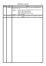
Страница 59: ... 2009 Revision U131 1 Page 39 Page 43 Page 44 Parts No of No 77 was D40 022 344 and quantity Q ty pcs unit was 3 Parts No of No 121 was Y45 611 045 Parts No of No 126 was M45 664 224 Parts No of No 128 was D40 033 346 No 133 Parts No D40 022 344 was added No 133 was No 77 Page 5 Section 3 Drying time old model 5 6 sec new model 3 5 sec was deleted ...

Отзывы: