


FREQROL Inverter Driver
GP-Pro EX Device/PLC Connection Manual
3
1
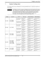
System Configuration
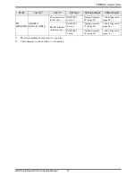
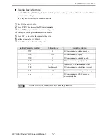
The following table lists system configurations for connecting Mitsubishi Electric Corporation External Devices
and the Display.
• If problems such as communication interruptions due to a disconnection of the signal
wire or malfunction of the Display cannot be detected on the inverter side, implement
a precautionary measure by using the inverter’s communication retry function or
communication check function. Refer to your External Device manual for details.
• Do not reset the inverter while communication is enabled. This may cause
malfunction. Prior to resetting the inverter, take the Display offline.
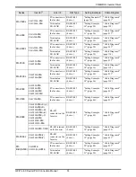
Series
Inverter
*1
Link I/F
SIO Type
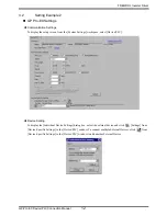
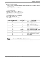
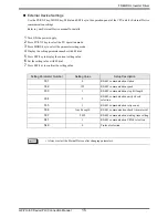
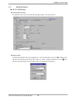
Setting Example
Cable Diagram
FR-A700
FR-A720-
K
FR-A740-
K
PU connector on
the Inverter
RS-422/485
(4 wire )
"Setting Example 1"
(page 10)
" Cable Diagram 1"
(page 62)
RS-485 terminal
on the Inverter
RS-422/485
(4 wire )
"Setting Example 2"
(page 12)
" Cable Diagram 2"
(page 66)
RS-422/485
(2 wire)
"Setting Example 3"
(page 14)
" Cable Diagram 3"
(page 72)
FR-A701
FR-A721-
K
PU connector on
the Inverter
RS-422/485
(4 wire )
"Setting Example 1"
(page 10)
" Cable Diagram 1"
(page 62)
RS-485 terminal
on the Inverter
RS-422/485
(4 wire )
"Setting Example 2"
(page 12)
" Cable Diagram 2"
(page 66)
RS-422/485
(2 wire)
"Setting Example 3"
(page 14)
" Cable Diagram 3"
(page 72)
FR-F700
FR-F720-
K
FR-F740-
K
PU connector on
the Inverter
RS-422/485
(4 wire )
"Setting Example 4"
(page 16)
" Cable Diagram 1"
(page 62)
RS-485 terminal
on the Inverter
RS-422/485
(4 wire )
"Setting Example 5"
(page 18)
" Cable Diagram 2"
(page 66)
RS-422/485
(2 wire)
"Setting Example 6"
(page 20)
" Cable Diagram 3"
(page 72)
FR-E700
FR-E720-
K
FR-E740-
K
FR-E720S-
K
FR-E710W-
K
PU connector on
the Inverter
RS-422/485
(4 wire )
"Setting Example 7"
(page 22)
" Cable Diagram 4"
(page 81)
*2
RS-422/485
(2 wire)
"Setting Example 8"
(page 24)
" Cable Diagram 5"
(page 92)
RS-485 terminal
on FR-E7TR
RS-422/485
(4 wire )
"Setting Example 7"
(page 22)
" Cable Diagram 8"
(page 124)
RS-422/485
(2 wire)
"Setting Example 8"
(page 24)
" Cable Diagram 9"
(page 130)
FR-V500
FR-V520-
K
FR-V540-
K
PU connector on
the Inverter
RS-422/485
(4 wire )
"Setting Example 9"
(page 26)
" Cable Diagram 4"
(page 81)
*2
Terminal on
FR-A5NR
RS-422/485
(4 wire )
"Setting Example
10" (page 28)
" Cable Diagram 7"
(page 118)