


FREQROL Inverter Driver
GP-Pro EX Device/PLC Connection Manual
62
5
Cable Diagrams
The cable diagrams shown below may be different from cable diagrams recommended by Mitsubishi Electric
Corporation. Please be assured there is no operational problem in applying the cable diagrams shown in this
manual.
•
The FG pin of the External Device body must be D-class grounded. Please refer to the manual of the External
Device for more details.
•
SG and FG are connected inside the Display. When connecting SG to the External Device, design the system
not to form short-circuit loop.
•
Connect the isolation unit if noise and interference affect communication.
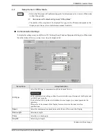
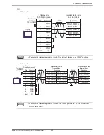
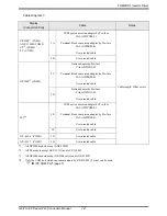
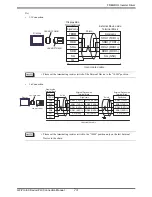
Cable Diagram 1
Display
(Connection Port)
Cable
Notes
GP3000
*1
(COM1)
AGP-3302B (COM2)
ST
*2
(COM2)
LT (COM1)
IPC
*3
*1
All GP3000 models except AGP-3302B
*2
All ST models except AST-3211A and AST-3302B
*3
Only the COM port which can communicate by RS-422/485 (4 wire) can be used.
)
"
IPC COM Port" (page 7)
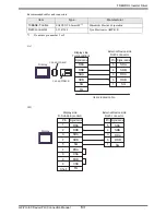
1A
COM port conversion adapter by Pro-face
CA3-ADPCOM-01
+
Terminal block conversion adapter by Pro-face
CA3-ADPTRM-01
+
User-created cable
Cable length: 500m or less
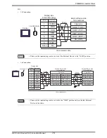
1B
User-created cable
GP3000
*4
(COM2)
*4
All GP3000 models except GP-3200 series and AGP-3302B.
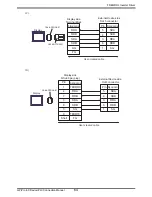
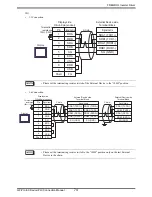
1C
Online adapter by Pro-face
CA4-ADPONL-01
+
Terminal block conversion adapter by Pro-face
CA3-ADPTRM-01
+
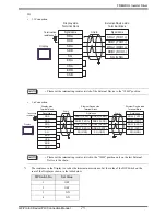
User-created cable
1D
Online adapter by Pro-face
CA4-ADPONL-01
+
User-created cable
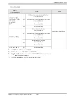
GP- 4106 (COM1)
1E
User-created cable


