


7Appendix
Inertia calculation method Appendix-138
7 Appendix
Appendix 1 : Inertia calculation method
An allowable moment of inertia in the mechanical interface at the tip of the robot arm is determined. If a load
exceeding the allowable moment of inertia is put, on the tip of the arm, vibration during operation and an overload
alarm may occur. Therefore, consider the matching/appropriateness of the hand and load to be mounted on the tip
of the arm for the robot specifications when you select a robot. The following describes the load inertia calculation
method.
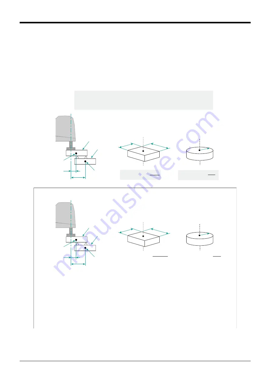
Calculate the total moment of inertia about the J4 axis.
I = Iz
1
+ Iz
2
+ W
1
L
1
2
+ W
2
L
2
2
L
1
L
2
W
1
W
2
I: total moment of inertia about the J4 axis
Iz: load inertia
W: mass (kg)
Rectangular shape
Cylindrical shape
a
2
+ b
2
Load inertia: Iz = W·
12
r
2
Load inertia: Iz = W·
2
[Calculation example]
a
b
r
Hand
Workpiece
Center of gravity
of the hand
Center of gravity
of the workpiece
Total moment of inertia about the J4 axis
I = 0.0068 + 0.0012 + 2.5 x 0.05
2
+ 1.5 x 0.1
2
= 0.030 kg·m
2
The calculation result (0.030 kg·m
2
) is greater than the allowable inertia (rating) of 0.01 kg·m
2
for RH-6FRH.
However, if the center of gravity of the hand is aligned with the axis of rotation of J4 and the workpiece is held directly below the J4
axis, both L
1
and L
2
become zero and the total inertia around the J4 axis is calculated as follows.
I = 0.0068 + 0.0012 = 0.008 kg·m
2
< 0.01 kg·m
2
The result is smaller than the allowable inertia.
㻵㼒㻌㼠㼔㼑㻌㼠㼛㼠㼍㼘㻌㼙㼛㼙㼑㼚㼠㻌㼛㼒㻌㼕㼚㼑㼞㼠㼕㼍㻌㼑㼤㼏㼑㼑㼐㼟㻌㼠㼔㼑㻌㼍㼘㼘㼛㼣㼍㼎㼘㼑㻌㼕㼚㼑㼞㼠㼕㼍㻘㻌㼏㼛㼚㼟㼕㼐㼑㼞㻌㼏㼔㼍㼚㼓㼕㼚㼓㻌㼠㼔㼑㻌㼍㼘㼕㼓㼚㼙㼑㼚㼠㻌㼛㼞㻌㼛㼠㼔㼑㼞㻌㼏㼛㼚㼐㼕㼠㼕㼛㼚㼟㻌㼒㼛㼞㻌㼠㼔㼑㻌㼔㼛㼘㼐㼕㼚㼓㻌㼟㼥㼟㼠㼑㼙㻚
50
100
2.5kg
1.5kg
Hand
Workpiece
0.15
2
+ 0.1
2
Load inertia: Iz
1
= 2.5×
= 0.0068kg·m
2
= 0.0012kg·m
2
12
0.04
2
Load inertia: Iz
1
=1.5×
2
150
100
40
Hand
Workpiece
Center of gravity
of the hand
Center of gravity
of the workpiece
Содержание CR800 Series
Страница 2: ......
Страница 154: ...Appendix 141 Specifications discussion material 7Appendix ...
Страница 155: ......