background image

40

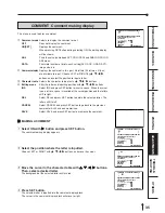
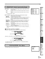
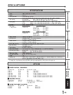
ANALOG COLOR ADJ

INPUT     COLOR/B&W  
BRT

:  0

   CONT

:  0

R-SUB :  0

C

R

G-SUB :  0

M

G

B-SUB :  0

Y

B

COLOR :  0
APT

:  0

CENTER
CANCEL

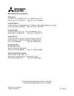
LAYOUT2&SYSTEM2

PRN V AREA (L2 ONLY)   0   (

±

10)

SEPARATE

OFF/ON

MARGIN CUT

OFF/ON

CHECK EXIT

OFF/ON

Hi/Mid/Low

Adjusts the colour depth of image by selected point.

POINT(Hi/Mid/Low)

Selects the point to adjust the colour depth.


(EXAMPLE)

Pointing lighter colour much lighter;
Set the setting level for POINT(Hi) and Hi higher.

NOTE

It takes time to set the gamma value by CPU. Wait until the normal display is shown
after pressing SET button.
It may take time to switch the program when the value of gamma setting is changed.

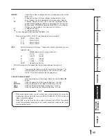
LAYOUT2&SYSTEM2 Layout and system setting display 2

PRN V AREA

Adjusts the vertical position of memory image.
Setting area -10 to 10 ( adjusts 2 lines each)

This menu is displayed only when IMAGES is set for 2 in L size paper.

PRN V AREA permits adjustment of the vertical position of the image so that the
clipped part of the image can be moved higher and lower.

SEPARATE

Selects whether a white frame is added to each print or not.

OFF

Prints without white frame. (A white frame appears according to the
setting of LAYOUT.)

ON

Prints with white frame.

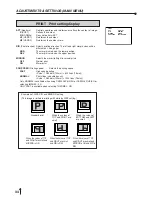
MARGIN CUT

Cuts the margin of the printed paper.

This function is very convenient to stick the printed image on the card.  The figure
shows S size print paper setting.

OFF

Margin is not cut.

ON

Margin is cut.

Only OFF is displayed when selecting THERMAL : ON.

CHECK EXIT

Selects whether this unit operates paper detecting function when
the printed paper is left at the print outlet or not.

OFF

Does not operate paper detecting function.

ON

Operates paper detecting function.

Only OFF is displayed when selecting THERMAL : ON.

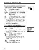
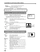
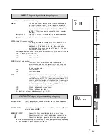
ANALOG COLOR ADJ   Analog colour adjustment display

This menu is used to adjust the image of analog input signal before storing in the
memory.

INPUT

Selects processing of video signal.

COLOR

Processes as colour video signal.

B&W

Processes as monochrome video signal. (The image is shown in
black and white.)
Select B&W when inputting monochrome signal.

BRT 

(Bright)

Adjust the brightness of the printing image.

CONT 

(Contrast)

Adjust the contrast of the printing image.

R-SUB

Adjusts red-subcontrast of the printing image.  Red is added with

]

 and blue is added with 

[

.

G-SUB

Adjusts green-subcontrast of the printing image.  Green is added
with 

]

 and pink is added with 

[

.

B-SUB

Adjusts blue-subcontrast of the printing image.  Blue is added with

]

 and yellow is added with 

[

.

COLOR

Adjusts density of the printing image.  The colour of the image gets
deeper with 

]

 and lighter with 

[

.

APT

Adjusts the contour of image. The contour is reinforced with 

]

 and

softened with 

[

.

CENTER

Initializes each setting.  When pressing 

]

, the values of BRT,

CONT, R-SUB, G-SUB, B-SUB, COLOR and APT will be reset to
centre value.

CANCEL

Cancels the change of ANALOG COLOR ADJ and resets to the
stored setting.

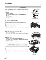
A

Gray part is
cut when
MARGIN
CUT is ON.

ADJUSTMENTS & SETTINGS (SERVICE MENU)

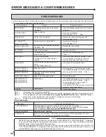
Содержание CP910E

Страница 1: ... the requirements of the EC Directive 89 336 EEC 73 23 EEC 93 42 EEC and 93 68 EEC The electro magnetic susceptibility has been chosen at a level that gains proper operation in residential areas on business and light industrial premises and on small scale enterprises inside as well as outside of the buildings All places of operation are characterised by their connection to the public low voltage p...

Страница 2: ...OFF symbol indicates connection to or disconnection from the mains at least for mains switches The Equipotentiality symbol identifies the terminals connected each other The poten tial of various parts of equipment or of a system is equalized The Alternating current symbol indicates that the equipment is suitable for alternating current only RISK OF ELECTRIC SHOCK DO NOT OPEN TO REDUCE THE RISK OF ...

Страница 3: ...2 or bigger length 2 5m or shorter cord with IEC60320 1 C13 type 250V 10A or higher rating connector and CEE 7 VII type 250V 10A or higher rating plug Use the video cable S video cable and or the wired remote control according to the recommendations as below in order to comply with safety and EMC standards The video cable shall be 2 m long or shorter 75Ω coaxial 3C 2VT or equivalent one with BNC p...

Страница 4: ...ious pages for safety and page 49 for accessories This page the previous pages for safety and page 49 for accessories This page the previous pages for safety and page 49 for accessories This page the previous pages for safety and page 49 for accessories Page 5 and 16 for print paper Page 49 for accessories WARNING The use of ACCESSORIES transducers and cables other than those specified with the ex...

Страница 5: ... interruptions and voltage variations on power supply input lines IEC EN 61000 4 11 Power frequency 50 60 Hz magnetic field IEC EN 61000 4 8 IEC EN 60601 test level 6 kV contact 8 kV air 2 kV for power supply lines 1 kV for input output lines 1 kV differential mode 2 kV common mode 5 UT 95 dip in UT for 0 5 cycle 40 UT 60 dip in UT for 5 cycles 70 UT 30 dip in UT for 25 cycles 5 UT 95 dip in UT fo...

Страница 6: ...n electromagnetic site survey a should be less than the compliance level in each frequency range b Interference may occur in the vicinity of equipment marked with the following symbol Compliance level 3 Vrms 3 V m NOTE1 At 80 MHz and 800 MHz the higher frequency range applies NOTE2 These guidelines may not apply in all situations Electromagnetic propagation is affected by absorption and reflection...

Страница 7: ...of the transmitter where P is the maximum output power rating of the transmitter in watts W according to the transmitter manufacturer NOTE1 At 80 MHz and 800 MHz the separation distance for higher frequency range applies NOTE2 These guidelines may not apply in all situations Electromagnetic propagation is affected by absorption and reflection from structures objects and people Separation distance ...

Страница 8: ... print 23 24 Separate print 25 Photo prints 25 External remote terminal 1 26 External remote terminal 2 27 Setting the functions Menu chart 28 29 Monitor display chart 28 29 Adjustments settings MAIN MENU 30 36 MAIN MENU items 30 Operating MAIN MENU 30 31 COLOR ADJ Colour adjustment display 32 LAYOUT Layout setting display 32 33 PRINT Print setting display 34 COMMENT Comment making display 35 36 M...

Страница 9: ...the inside of the unit unplug the power cord from the source outlet and contact the sales dealer If used without corrective measures the unit may be damaged In the interest of safety avoid handling of liquids near the unit DO NOT REMOVE THE CABINET Touching internal parts is dangerous besides it may lead to malfunction Contact the sales dealer to carry out internal checks and adjustments Before op...

Страница 10: ...e OPERATING AMBIENT TEMPERATURE RANGE The operating ambient temperature range is 41 F 104 F 5 C to 40 C and humidity of 20 80 RH When using the unit on the system rack be sure to keep this ambient temperature inside the rack FOR LONG OPERATING LIFE UNSUITABLE MATERIALS FOR THE COLOUR VIDEO COPY PROCESSOR Coat flaking and deformation are likely to occur if the unit is wiped with chemical dusters be...

Страница 11: ...uest such circuit diagrams component part lists descriptions calibration instructions or other information which will assist the USER s appropriately qualified technical personnel to repair those parts of the EQUIPMENT which are classified by the manufacturer as repairable The use of ACCESSORY equipment not complying with the equivalent safety requirements of this equipment may lead to a reduced l...

Страница 12: ...g the printing operation stops and CHANGE PAPER is displayed on the monitor Install new paper at this time Store the printed paper in a place with low humidity free from a direct sunlight If the paper absorbs nonvolatile organic solvents alcohol ester ketone etc the print may be discoloured Particularly if the paper comes in contact with soft vinyl chloride such as a transparent tape it quickens d...

Страница 13: ... printing reduces a time of exchanges POSSIBLE PRINTING IN HIGH QUALITY High quality print is available in sublimation dye thermal method which is superior in repeatability of images It also employs 256 gradients and about 16 700 000 colours in each YMC 325 PPI HIGH RESOLUTION 325 PPI Pixel Per Inch high resolution clears the image data Precise illustrations and photo images can be printed sharply...

Страница 14: ...tents Be careful not to drop the contents C O L O R V I D E O C O P Y P R O C E S S O R 3 3 3 3 3 Take the unit out of the box carefully Make sure to keep the unit horizontally 4 4 4 4 4 Unwrap the packing 2 2 2 2 2 CONTENTS Make sure to check the supplied contents on the cushion COLOURVIDEO COPY PROCESSOR PRINT PROG MENU CLEAR MONITOR MEMORY MEMORY PAGE STOP SET COLOR FIELD ADJUST FRAME DISPLAY P...

Страница 15: ...he monitor screen switches between the picture of the input signal source image and the memorized image When pressing MEMORY button while holding this button print paper will be fed and cut automatically and the mechanism will be initialized Make sure to press MONITOR button first or a new image will be memorized A A A A A MEMORY BUTTON Press to memorize the image to be printed When signal is not ...

Страница 16: ...nal It is necessary to make a circuit for remote control to use the function See page 26 3 3 3 3 3 S VIDEO INPUT OUTPUT TERMINAL Use these terminals to connect to S VIDEO signal equipment See pages 11 AC LINE REMOTE S VIDEO IN OUT VIDEO IN OUT 1 3 2 5 4 4 4 4 4 4 VIDEO INPUT OUTPUT TERMINAL Use these terminals to connect this unit to VIDEO signal equipment See page 11 5 5 5 5 5 AC LINE SOCKET Conn...

Страница 17: ...e pages 28 29 C C C C C CLEAR BUTTONS Press to eliminate all or a part of memorized images D D D D D MONITOR BUTTON Press to switch the image of the input signal and the memorized image E E E E E MEMORY BUTTON Use to memorize the image to be printed The memorized image is displayed on the monitor screen for one second then the image of the input signal is displayed 1 1 1 1 1 COLOR ADJUST BUTTON Pr...

Страница 18: ...n be set by the menu screens displayed on the monitor Connection with a monitor Connection with VIDEO S VIDEO signal equipment Connect this unit with a monitor to check the images to be printed and the images stored in memory The following example shows the connection with a video signal and S video signal equipment Connect with the necessary signal equipment Make sure to turn off the power of the...

Страница 19: ... S Size 130 Surface laminated colour print for ID photo CK900L4P HX EU L Size 90 Surface laminated colour print for ID photo 2 2 2 2 2 THERMAL PAPER Product name Print size No of prints Usage KP65HM CE S L size S size Approx 200 Thermal print L size Approx 125 2 2 2 2 2 PAPER INK SHEET CASSETTE Product name Ink sheet size No of prints Usage PKC900S S size 200 Colour print PKC900L L size 130 Colour...

Страница 20: ...per roller with gear on the left Press the folder 1 as shown right and set the print paper roller 2 2 2 2 2 Set the other side of roller without gear 3 3 3 3 3 Remove the seal and insert the edge of the print paper right below the roller cover with arrow marks towards the front panel Make sure to insert the paper straight 4 4 4 4 4 Feed the print paper through the paper outlet with your hand 5 5 5...

Страница 21: ...se defective paper Do not use the bent or wrinkled paper Adjust the paper position correctly When the paper is fed out skewed from the print exit adjust the paper position so that it is fed out straight Do not slack the roll paper Set the paper tightly to remove any slack Make the paper side even If the side of the print paper is uneven or the core is sticking out the amount of paper feeding after...

Страница 22: ...he print paper The printing mechanism is initialized Projected part IC holder NOTE Do not remove the IC chip or IC holder from the ink sheet Removal of the IC will stop the printer from functioning correctly Set the projected part of the IC holder to the correct position as shown below 2 2 2 2 2 INSTALLING THE INK CASSETTE 1 1 1 1 1 Eliminate any slack of the ink sheet Hold the coloured roller and...

Страница 23: ...uses color of print paper to come off and to be stained Never store print paper in places that are close to heater hot humid or dusty Keep print paper in a place where Temperature 5 C 30 C Humidity 20 60 RH NOTE If the power is turned on and AUTO FEED CUT on SYSTEM SETUP menu is set to ON SET PAPER on the monitor disappears when print paper is inserted under the roller For AUTO FEED CUT setting re...

Страница 24: ...the menu displayed on the monitor screen Unless the input signal is changed it is not necessary to select the input signal every time 1 1 1 1 1 Press MENU button MAIN MENU is displayed 2 2 2 2 2 Press button to select INPUT 3 3 3 3 3 Press button to select VIDEO or S VIDEO 4 4 4 4 4 Press SET button SAVE PRG 1 2 3 CANCEL is selected This menu lets you select a program memory 1 3 to store your new ...

Страница 25: ... to select the print size every time 1 1 1 1 1 Press MENU button to display MAIN MENU 2 2 2 2 2 Press button to select LAYOUT 3 3 3 3 3 Press button LAYOUT is displayed Normally MODE is selected when opening LAYOUT When other item is selected press or button to select MODE 4 4 4 4 4 Press button to select AUTO or S Select L or S when THERMAL is set to ON Select AUTO for normal setting Select S to ...

Страница 26: ... the display changes to show the Field or Frame mode Frames are shown as ABC FRAME and since one Frame consists of two Fields the Frame letter is shown in green along with the Field display as 1 or 2 in green as ABC FIELD1 ABC FIELD2 Press MEMORY PAGE button to advance the Memory Page to the next Field or Frame The selected page number is shown in green The memory page in which the next image will...

Страница 27: ...ed on the monitor However only the selected page can be printed 2 2 2 2 2 IMAGE MEMORIZING WITH PAGE INCREMENT SET TO PAGE When INCREMENT is set to PAGE automatic memory page advance system the followings are the memory operations Every time pressing MEMORY button the memory page is switched in order ofA B C and image will be memorized in it To memorize an image on a memory page you selected press...

Страница 28: ...LD PRINT EXAMPLE 2 2S 4 16 2 1 1 2 3 4 MULTI 1 2 3 4 5 6 7 8 9 10 11 12 13 14 15 16 1 page 2 pages 1 page 2 pages 2 pages MODE PHOTO1 FRAME FIELD PRINT EXAMPLE S size print CARD 3 x 4 5 x 5 3x3 5 MULTI 3 pages 6 pages 3 pages 6 pages 3 pages 6 pages 3 pages 6 pages 1 2 3 4 5 6 7 8 9 10 11 12 13 14 15 16 1 2 3 4 1 2 1 2 3 4 5 6 MODE SAME Multi printing the same images FRAME FIELD PRINT EXAMPLE 2 2S...

Страница 29: ...selecting C the set number on the monitor will be counted down every time one sheet is printed When printing is completed the counter will be reset to the original set number This will not reset when turning off the power It will not be reset to 1 If you wish to stop printing Press PRINT Q ty and buttons After printing the current page the counter will be reset to 1 Pressing PRINT Q ty and buttons...

Страница 30: ...ecial prints are given For each setting see pages 28 29 MULTI PRINT MULTI PRINT is the function which 2 4 or 16 images can be printed on a sheet Use LAYOUT of MAIN MENU for setting For the setting refer to pages 32 33 For PHOTO1 setting refer to PHOTO PRINTS on page 25 2 2S 4 16 S size prints L size prints MODE SAME DIFF MODE DIFF When setting IMAGES to 2 2S 2 images are available to be stored in ...

Страница 31: ...ress button to determine the position to store the image The image is stored in the selected memory page The position number where the image can be stored is indicated in yellow 2 2 2 2 2 WHEN SETTING TO MODE SAME IMAGES 4 Only one image will be displayed on the monitor screen 1 1 1 1 1 Press DISPLAY button to display the set condition 2 2 2 2 2 Press MONITOR button and select the source image LIV...

Страница 32: ... on the monitor and the printed image The image size changes according to the SIZE in LAYOUT menu The setting just before printing applies to all the multi print images PHOTO PRINTS PHOTO print is a function to print the images on the photo size 3 x 4 cm 5 x 5 cm 3 x 3 5 cm and CARD size 2 x 1 5 cm CARD size print is suited to stick on a business card Use LAYOUT of MAIN MENU for setting Refer to p...

Страница 33: ...OW from HIGH the image is stored in memory When the signal has been LOW for 15ms or more the image is stored in memory See page 42 43 3 BUSY1 Refer to the BUSY LEVELsetting of REMOTE SET in SERVICE MENU See page 43 When the signal from BUSY terminal is received with TTL level keep the following IOL 2mA or less IOH 1mA or less IOL means the current flowing into the unit at Low output IOH means the ...

Страница 34: ...s received with TTL level keep the following IOL 2mA or less IOH 1mA or less IOL means the current flowing into the unit at Low output IOH means the current flowing out of the unit at High output Just after completing printing there is a period that memory signal is not accepted 5 2 1 4 3 67 8 Pin No 22kΩ 22kΩ 10kΩ 100Ω DTC124EK DC5V 1kΩ 74LVC125 10kΩ 100Ω DC5V To VCP To VCP From VCP To VCP 2 6 3 ...

Страница 35: ... selecting MODE PHOTO1 IMAGES card 3 4 5 5 3 3 5 are available Only NORMAL is available when selecting IMAGES 2S or using CK900S4P HX EU or CK900L4P HX EU Only FAST is available when selecting THERMAL ON L S is displayed when selecting THERMAL ON 2S is not displayed when selecting THERMAL ON PRG 1 Q ty 1 VIDEO S VIDEO ABC FRAME ABC FIELD1 2 LIVE MEMORY MAIN MENU INPUT VIDEO S VIDEO COLOR ADJ LAYOU...

Страница 36: ...ADJ INPUT OUTPUT KEY SET REMOTE PREVIOUS ERROR SAVE PRG 1 2 3 CANCEL SYSTEM SETUP INCREMENT OFF PART PAGE BUZZER OFF T1 T2 REMAINING Q ty 10 REMAIN NOTICE OFF BZ PR B P REMAINING SCREEN OFF ON ERROR SCREEN OFF ON AUTO FEED CUT OFF ON THERMAL OFF ON PAPER HOLD OFF ON INIT PRG ALL MAIN SERVICE INITIALIZE OFF GO SET GAMMA ADJ INIT CLEAR COLOR ALL EACH SELECT R G B Hi 0 Mid 0 Low 0 POINT 64 128 192 LA...

Страница 37: ...ories OPERATING MAIN MENU Use the buttons on the remote control unit to display MAIN MENU and select and set functions 1 1 1 1 1 Press MENU button to display MAIN MENU 2 2 2 2 2 Select your desired item by pressing or button 3 3 3 3 3 Press button to open a sub menu 4 4 4 4 4 Select an item you wish to adjust by pressing or button MAIN MENU INPUT VIDEO S VIDEO COLOR ADJ LAYOUT PRINT COMMENT MEMORY...

Страница 38: ...o cancel the setting select CANCEL and press SET button 8 8 8 8 8 Press SET button When selecting PRG1 to set 1 is chosen When memorizing in a different program memory number select the number of the program As the program is replaced it is recommended not to choose the program number which has been selected in the step 7 The memorized program will be selected by pressing PROG button and the image...

Страница 39: ...ted image When SELECT is changed from COLOR to B W the set values of R SUB G SUB and B SUB function as the density of gray colour LAYOUT Layout setting display MODE Selects the print size Normally select the ink sheet size which is installed in this unit See page 12 for the print paper AUTO L size ink sheet When S size ink sheet is installed S size is automatically set S S size ink sheet or S size...

Страница 40: ...rea Printed image size of 1 image mode mm S size L size W 100X75 125X94 M 94X70 118X89 N 90X68 113X85 USER Optional size by user Part of the image may be clipped from the print depending on the print size COPY Copies a printed image size which is set W M or N in size The selected setting level is displayed as TOP BOTTOM LEFT and RIGHT These levels become the changing base TOP BOTTOM LEFT RIGHT Set...

Страница 41: ...not perform APT H1 HARD 1 Reinforces the contour H2 HARD 2 Reinforces the contour more DIR Print direction Selects printing direction The left and right margin sizes will be different on L size paper NOR The margin is made on the lower position REV The margin is made on the upper position MIRROR Selects the mirror left right inversed prints OFF Normal print ON Mirror print PRN SPEED Printing speed...

Страница 42: ...ct CANCEL and press SET button to go back to the previous comment which has been memorized SAVE Select SAVE and press SET button to memorize the comment 2 2 2 2 2 MAKING A COMMENT 1 Select ON with button and press SET button The comment editing display appears 2 Select the position where the letter is inputted Choose LEFT or RIGHT with buttons and move the cursor 3 Move the cursor to the character...

Страница 43: ...yed on the memory image H POSI Changes the horizontal start position of input signal The whole data image can be moved horizontally by changing the setting number Setting area 8 8 When setting minus value too large the right side of the memory image is clipped on the monitor However it is printed normally V POSI Changes the vertical start position of input signal The whole data image can be moved ...

Страница 44: ...or button 6 6 6 6 6 Press or button to select an item or change value 7 7 7 7 7 Press SET button SERVICE MENU is displayed SAVE PRG 1 2 3 CANCEL is selected This menu lets you select a program memory 1 3 to store your new settings 8 8 8 8 8 Press or button to select the program memory number of 1 2 or 3 to store the setting The program is replaced In case of keeping the stored program do not selec...

Страница 45: ...s when closing the door PR Informs by printing a red mark under the comment area on the print B P The buzzer sounds three times and a red mark is printed under the comment area on the print When selecting SELECT B W in COLOR ADJ the red mark is printed in black and white REMAINING SCREEN Selects whether displaying the remains of ink sheet on the monitor or not OFF Does not display the remains of i...

Страница 46: ...ELECT Is displayed when selecting EACH in COLOR R Adjusting gamma level for red G Adjusting gamma level for green B Adjusting gamma level for blue Changing gamma curve Use the buttons on the remote control unit to select the Hi Mid Low gamma point to set Also use buttons to input setting level PAPER HOLD AUTO CUT MARGIN CUT With ink cassette THERMAL OFF OFF OFF OFF ON ON OFF OFF ON ON Not displaye...

Страница 47: ...ot cut ON Margin is cut Only OFF is displayed when selecting THERMAL ON CHECK EXIT Selects whether this unit operates paper detecting function when the printed paper is left at the print outlet or not OFF Does not operate paper detecting function ON Operates paper detecting function Only OFF is displayed when selecting THERMAL ON ANALOG COLOR ADJ Analog colour adjustment display This menu is used ...

Страница 48: ... available AGC Automatic gain control This function is to automatically adjust a dark picture in brightness and print with sharp contrast Peak level of an input signal is detected and signal width is standardized to the appropriate value OFF AGC is invalid ON AGC is available DCF This function selects whether separating the composite video signal or not When inputting the monochrome signal set thi...

Страница 49: ...ote terminal is switched to low level from high for the first time a memory image is displayed Then at the second time a source image is displayed and the memory image is printed Do not change the MULTI setting after memorizing an image MEM STOP Memory and Stop OFF The next image is overlaid in the memory PART The next image can not be overlaid in the memory when all parts of a page become full To...

Страница 50: ...nals 1 and 2 on the rear panel LOW The VCP cannot accept the remote input signal when the signal is LOW HIGH The VCP cannot accept the remote input signal when the signal is HIGH The default setting is HIGH BUSY 1 2 SELECT Selects when the BUSY signal is outputted from the remote terminals 1 and 2 on the rear panel PRINTING Outputs BUSY signal during printing MECHA ERR Outputs BUSY signal when a m...

Страница 51: ...e temperature of the thermal head becomes too high IC chip is not installed The data in IC chip cannot be read correctly IC chip and the ink mark are not the same A wrong media type is set Paper jam occurs Paper jam occurs when selecting THERMAL ON Paper is left in the paper outlet Other defects Other defects Messages PUSH FEED CUT MECHA INITIALIZE PRINT STOP Causes and countermeasures Indicated w...

Страница 52: ...CREMENT OFF or AUTO CLEAR OFF Store the image in the memory after pressing the CLEAR button on the remote control unit According to the setting conditions the image can be stored in the memory by setting INCREMENT to PART or PAGE AUTO CLEAR to AFT PRN or pressing the PRINT button Is the memory full in the status of MEM STOP ON Press CLEAR button on the remote control unit and store the image again...

Страница 53: ...nnot be operated Is the plug of the remote control unit disconnected from its terminal on the unit Connect the plug of the remote control unit to the REMOTE terminal on the unit The supplied remote control unit can not be used by connecting to the external remote terminal on the rear panel of this unit Is the wired remote control unit for this unit accessory used Use the remote control unit for th...

Страница 54: ...emove the print paper as shown right 4 4 4 4 4 Cut the defective part of the print paper with scissors 5 5 5 5 5 Cut both edges of the print paper 6 6 6 6 6 Install the print paper Refer to pages 12 13 NOTE To feed the print paper press MEMORY button while pressing MONITOR button When carrying out this procedure make sure to press MONITOR button first If MEMORY button is pressed first a new image ...

Страница 55: ... 4 Wipe the ink sheet sensor reflection plate Clean the metal reflection plate Wipe with tissue paper etc which is soaked in a small amount of alcohol carefully 5 5 5 5 5 Wipe the head Cleaning the part under the thermal head which develops heat Wipe the head cleaning part carefully with tissue paper etc which is soaked in a small amount of alcohol NOTE Do not damage the thermal head When the symp...

Страница 56: ...terminal Mini Din 8 pin stereo mini jack Input frequency H frequency 15 75 kHz V frequency 50 Hz Power supply AC 220V 240V 50Hz Power consumption 1 2A AC220V 240V 50Hz during printing 0 3A when not printing Installation conditions Temperature 5 C 40 C 41 F 104 F Humidity 20 80 RH No dewing Operation altitude Within Horizontal 5 Outside dimensions 280 W x 150 H x 400 D mm Weight 11kg Accessories Po...

Страница 57: ...33 1 55 68 57 31 Italian Branch Centro Direzionale Colleoni Palazzo Perseo Ingresso 2 Via Paracelso 12 20041 Agrate Brianza Milano Italy Phone 39 03960531 FAX 39 0396053214 Benelux Branch Nijverheidsweg 23a 3641 RP Mijdrecht Nederland Phone 31 0 297 282461 FAX 31 0 297 283936 Spanish Branch Barcelona Ctra de Rubí 76 80 Apdo 420 08190 Sant Cugat del Vallés Barcelona Spain Phone 34 93 565 3154 FAX 3...

Отзывы: