E-23
ENGLISH
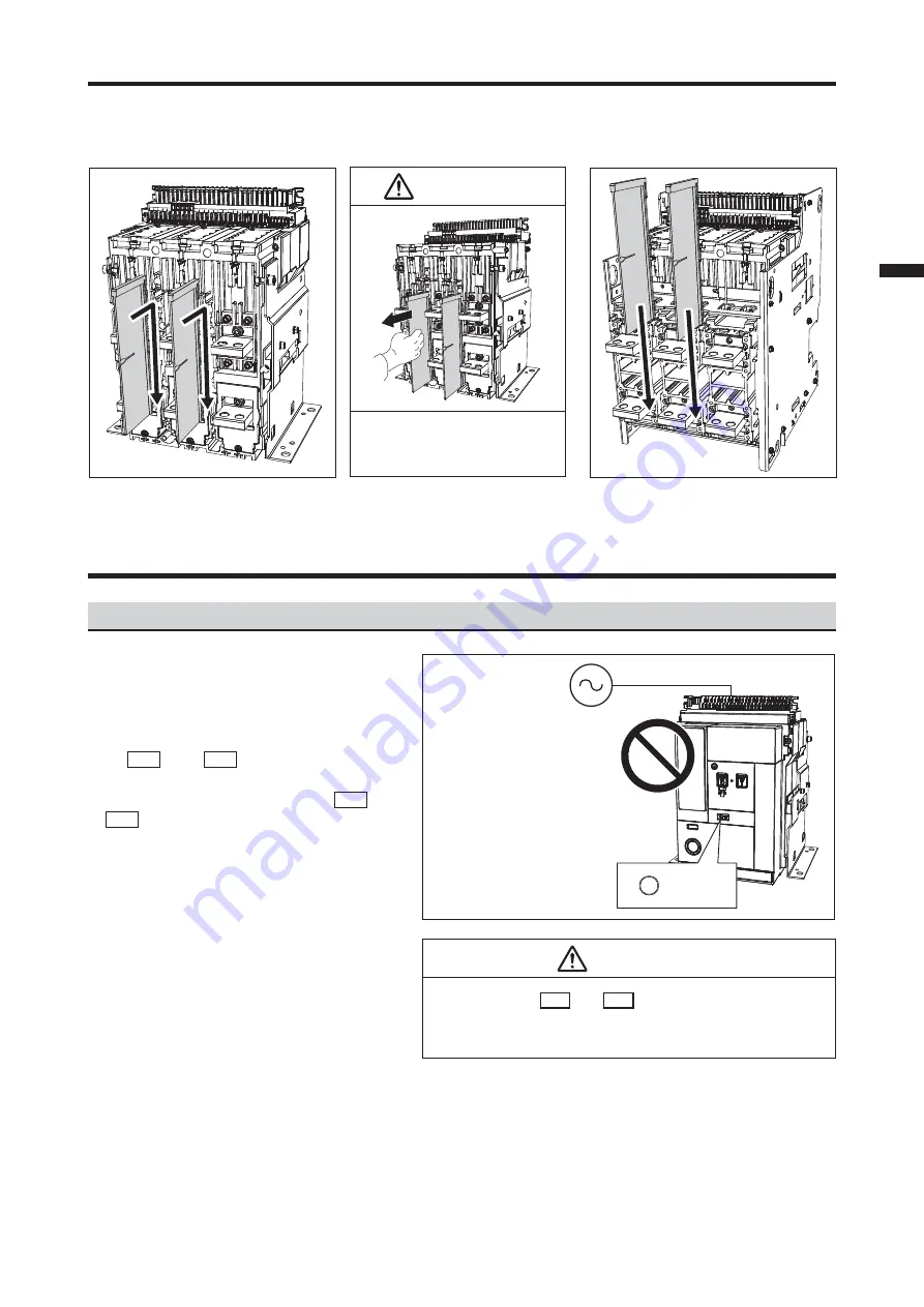
9. Attachment of the Interphase barrier
Insert the Interphase barriers in the slot on the circuit breaker.
■
Fixed type
After inserting, pull the interphase
barriers to check that the barriers
are correctly installed in the slot.
CAUTION
■
Drawout type
When the following conditions are satisfied,
the ON operation can be operated.
1. The circuit breaker is OFF.
2. The voltage for the ON operation is applied
to A1 and A2 of the control circuit
terminal block. Set the voltage capacity and
power supply capacity applied to A1 and
A2 by following the table of Circuit breaker
(solenoid) control rating.
3. The state without the OFF instruction
(following conditions)
• The voltage is not applied to the Shunt trip
device (SHT).
• The circuit breaker is not locked mechani-
cally by the Cylinder lock (CYL) or Castell
lock (CAL).
• The voltage is applied to the Under voltage
trip device (UVT).
• The circuit breaker is not tripped.
• When the padlock is used, the padlock of
the OFF button is released.
10. Opening/Closing operation
10.1 Conditions allowable for the closing operation
OFF
OFF instructions
Circuit breaker (solenoid)
control voltage
When connecting a control
circuit terminal block,
refer to page 43.
110-125 V AC
220-250 V AC
110-125 V DC
220-250 V DC
CAUTION
Apply voltage to A1 and A2 on the control circuit terminal
block within the specified operating voltage of the circuit breaker.
Failure to do so may result in malfunction of the circuit breaker.


