
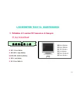
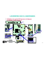
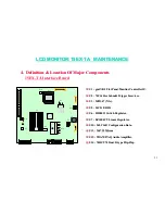


LCD MONITOR 15EX
LCD MONITOR 15EX
-
-
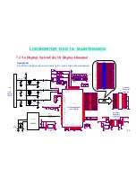
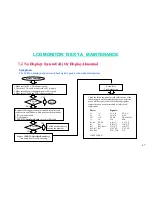
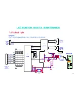
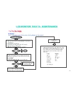
TA MAINTENANCE
TA MAINTENANCE
38
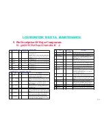
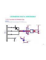
Test Pins
Pin Name I/O
Drive
Current
Description
3 PSCAN
in
Enable automatic PCB assembly test. When this input is
pulled high, the
automatic PCB assembly test mode is
entered. An internal pull-down resistor
drives this input
low for normal operation.
155 SCAN_IN1 in
Scan input 1 used for automatic PCB assembly testing.
157 SCAN_IN2 in
Scan input 2 used for automatic PCB assembly testing.
159 SCAN_OU
T1
out
Scan output 1 used for automatic PCB assembly testing.
160 SCAN_OU
T2
out
Scan output 2 used for automatic PCB assembly testing.
153 Reserved
154 Reserved
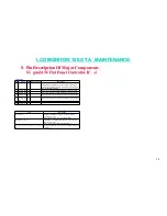
VDD / VSS for Core Circuitry, Host Interface, and Panel/Memory Interface
Pins Description
65, 40, 33, 12
PVDD4 ~ PVDD1 for panel / memory interface.
Connect to +3.3V.
Must be the same voltage as the CVDD’s.
149, 108, 58, 21, 11
SRVDD2-1, CVDD4, CVDD2-1 for core circuitry.
Connect to +3.3V.
Must be the same voltage as the PVDD’s.
158, 151, 140, 126, 114, 72, 61, 49, 41, 30,
18, 8, 1
Digital grounds for core circuitry and panel / memory
interface.
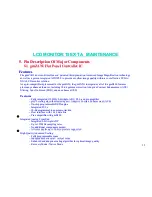
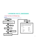
5.
5.
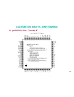
Pin Description Of Major Components
Pin Description Of Major Components
5.1 gmZAN1 Flat Panel Controller IC
5.1 gmZAN1 Flat Panel Controller IC
-
-
4
4
Содержание 15EX-TA
Страница 8: ...LCD MONITOR 15EX LCD MONITOR 15EX TA MAINTENANCE TA MAINTENANCE 7 1 2 13 COMPATIBLE TIMING CHART...
Страница 9: ...LCD MONITOR 15EX LCD MONITOR 15EX TA MAINTENANCE TA MAINTENANCE 8 1 2 14 MAIN OSD MENU...
Страница 10: ...LCD MONITOR 15EX LCD MONITOR 15EX TA MAINTENANCE TA MAINTENANCE 9...
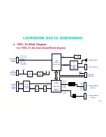
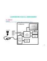
Страница 16: ...LCD MONITOR 15EX LCD MONITOR 15EX TA MAINTENANCE TA MAINTENANCE 15 1 3 HARDWARE SYSTEM BLOCK DIAGRAM...
Страница 62: ......


