background image

14

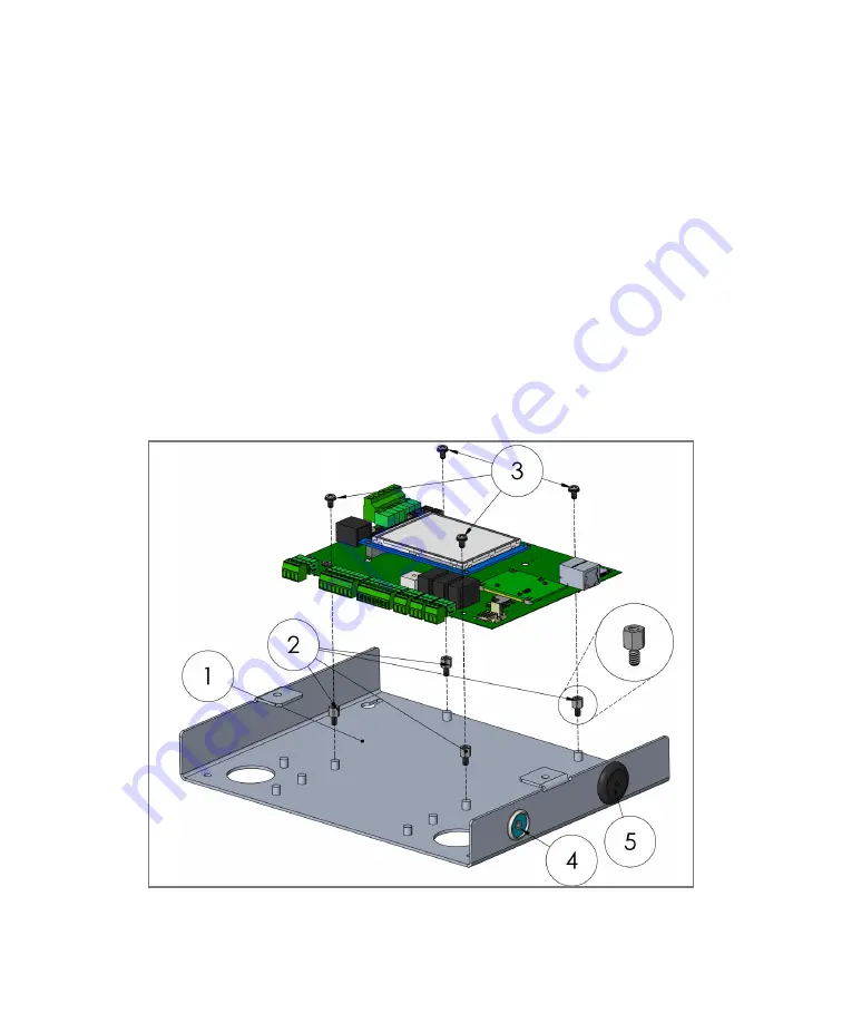
FlatPak Retrofit (see Figure 4)

1. Remove Legacy PCB hardware from existing FlatPak enclosure.
2. Extend standoffs by installing the four included standoffs (1/4” x #6–32) on 

top of the existing standoffs on the enclosure back plane. 

3. Secure the MyDro PCB into the enclosure by placing it on top of the           

extended standoffs, use existing #6–32 screws. 

4. Remove existing key reader and replace it with the one supplied. Terminate 

the new key reader at the bottom right side of the PCB.

5. Remove the old noisemaker and fill the hole with the supplied knock-out plug. 

The PCB includes an onboard noisemaker.

6. Replace lid with new one supplied when installation and testing is complete.

Figure 4: 

FlatPak Retrofit

Содержание MyDro 150

Страница 1: ...150 850 Upgrade Manual PMS 660 Contact tech support if plans change and when RTU is ready to be put in production This RTU upgrade is set to be installed at this location...

Страница 2: ...sponding document on our website We encourage you to take advantage of our quarterly newsletters training videos and weekly webinars Visit 123mc com to contact us or learn more about our training reso...

Страница 3: ...y Power 6 Auxiliary Power 6 Digital Inputs 8 Wet Well Module 8 Analog Inputs 10 Output Relays 11 I O Expansion 12 Chapter 3 Enclosure Installation 13 Rewiring 13 Configuration Adjustments 17 Configura...

Страница 4: ...previous boards so most wires will simply need to be reterminated and the MyDro features removable terminals for convenience The MyDro may require slightly different wiring considerations than the M11...

Страница 5: ...offs Knockout plug NEMA 1 Standoff mount 2 Knockout plugs Metal lid with window NEMA 4 Plastic lid for MyDro 4 1 2 standoffs 1 Additional key reader NEMA 4X Solar Enclosure Plastic lid for MyDro 8 1 2...

Страница 6: ...o capture the wiring of your existing RTU Individually label non obvious conductors Power In The top two terminals on the left are generally where power from the 120 volts to 12 VAC transformer enters...

Страница 7: ...Mount the antenna outside and high as possible preferably above the roof or other objects Mount the antenna underground in a dry well or inside a canned lift station Mount the antenna above all metal...

Страница 8: ...ace on the left side of the printed circuit board There were two versions of the WWM green older and red newer The MyDro does not directly support either version of the WWM but does support the option...

Страница 9: ...9 Figure 1 Using Wet Well Module with MyDro Figure 1b Using Safe Module Plus with MyDro...

Страница 10: ...e as 0 12 or 24 VDC Most analog instruments are rated for a broad range of voltages typically 10 30 VDC Selecting the 24 volt option makes voltage starvation situations much less likely when multiple...

Страница 11: ...is 30 volts maximum current is 5 amps We discourage high voltage AC inside of the Mission enclosure for safety and induced voltage reasons see Figure 3 Warning The MyDro relay normally open N O and no...

Страница 12: ...case of the FlatPak enclosure this is not optional The MyDro expansion modules support the same or better I O characteristics than the Legacy modules Table 1 Expansion Module Difference Chart Legacy...

Страница 13: ...ds and either terminate them to the corresponding terminal or temporarily insulate them Repeat for battery leads 2 Unscrew the SMA connector from the antenna connector 3 Remove the four screws holding...

Страница 14: ...CB into the enclosure by placing it on top of the extended standoffs use existing 6 32 screws 4 Remove existing key reader and replace it with the one supplied Terminate the new key reader at the bott...

Страница 15: ...supplied Use the holes for screwdriver access 3 Install MyDro mainboard on adapter bracket Secure with existing 6 32 screws 4 Remove existing key reader and noisemaker and replace with knockout plugs...

Страница 16: ...x 6 32 to secure the PCB to enclosure backplate 4 Place the MyDro cover over the PCB and use the four 6 32 screws to secure cover 5 Replace lid with new one supplied when installation and testing is...

Страница 17: ...on current sensor no EOL resistor broken wire or failed sensor will show as wire fault Load Sensor NF strap on current sensor no EOL resistor no wire supervision Runtime for items like pumps where st...

Страница 18: ...on Relay Communication Failure De energize generally appropriate if pumping into a pressure tank No change generally appropriate if tank can spill See Best Practices for Remote Control Applications do...

Страница 19: ...al and confirm proper operation As a reminder the N O and N C termi nals on the output relays are opposite that of the Legacy RTU 3 Confirm all automated remote control functions are working properly...

Страница 20: ...______________________________ _______________________________________ _______________________________________ _______________________________________ _______________________________________ _________...

Страница 21: ...______________________________ _______________________________________ _______________________________________ _______________________________________ _______________________________________ _________...

Страница 22: ...______________________________ _______________________________________ _______________________________________ _______________________________________ _______________________________________ _________...

Страница 23: ...______________________________ _______________________________________ _______________________________________ _______________________________________ _______________________________________ _________...

Страница 24: ...Web 123mc com Technical Support 877 993 1911 option 2 techsupport 123mc com setupforms 123mc com Sales sales 123mc com 877 993 1911 option 4 MUM 2104...

Отзывы: