background image

Power Indicator Codes

11

Power Indicator Codes

An LED indicator on the power button indicates when power is supplied to the 
appliance and the appliance is operational.

Redundant power supplies have an indicator that shows whether power is present 
or whether a power fault has occurred. 

Not lit—AC power is not connected.

Green—In standby mode, indicates that a valid AC source is connected to the 
power supply and that the power supply is operational. When the appliance is 
on, also indicates that the power supply is providing DC power to the 
appliance.

Amber—Indicates a problem with the power supply.

Alternating green and amber—When hot-adding a power supply, indicates that 
the power supply is mismatched with the other power supply (a High Output 
870-W power supply and an Energy Smart 570-W power supply are installed in 
the same appliance). Replace the power supply that has the flashing indicator 
with a power supply that matches the capacity of the other installed power 
supply.

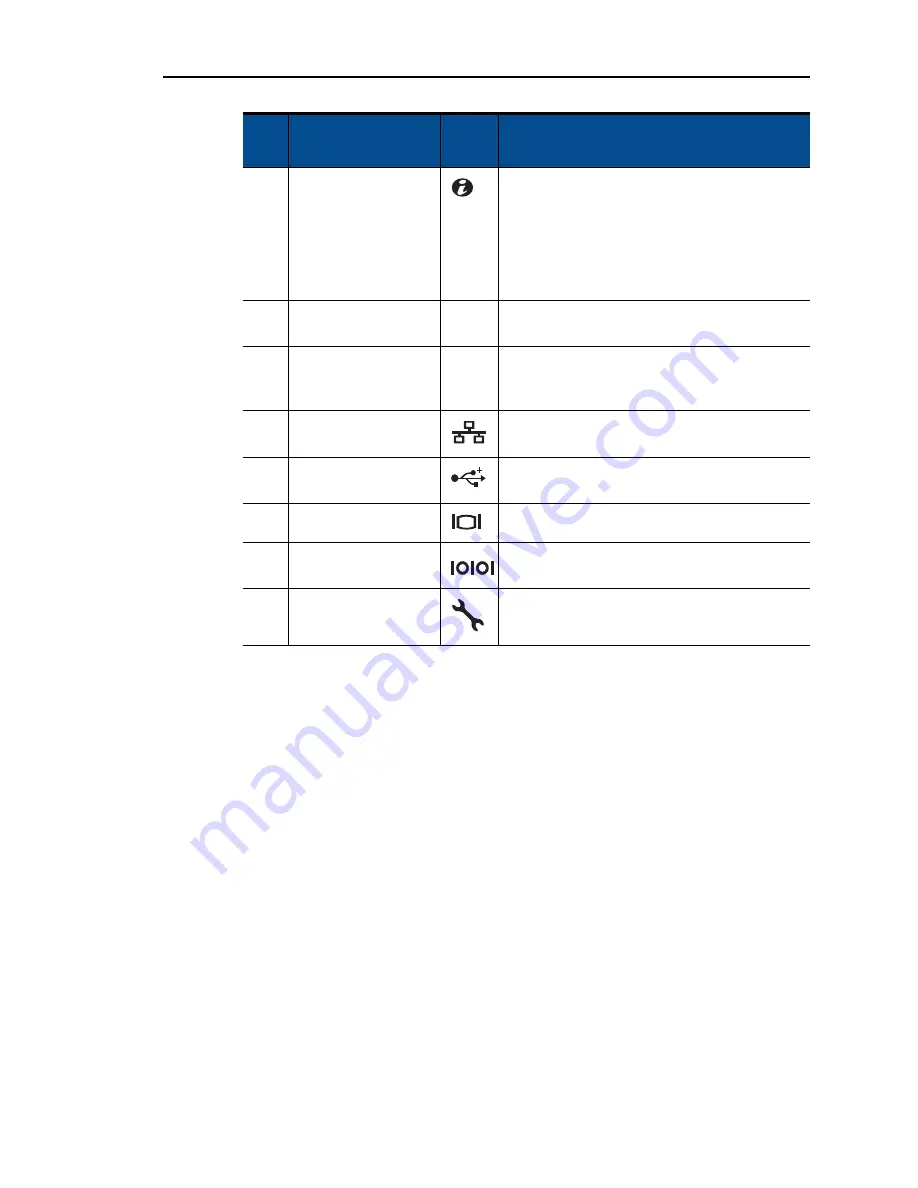
7

system identification 
button

The identification buttons on the front and 
back panels can be used to locate a particular 
appliance within a rack. When one of these 
buttons is pushed, the LCD panel on the front 
and the appliance status indicator on the back 
flash blue until one of the buttons is pushed 
again.

8

appliance status 
indicator


Provides a power on indicator for the back of 
the appliance.

9

appliance status 
indicator connector


Connector for attaching a appliance indicator 
extension cable that is used on a cable 
management arm

10

Ethernet connectors 
(4)

Integrated 10/100/1000 NIC connectors

11

USB connectors (2)

Connects USB devices to the appliance. The 
ports are USB 2.0-complaint.

12

video connector

Connects a VGA display to the appliance.

13

serial connector

Connects a serial device to the appliance.

14

iRAC6 Enterprise 
port 

Dedicated management port for the iRAC6 
Enterprise card.

Item

Indicator, Button, or 

Connector

Icon

Description

Содержание RazorSafe 700

Страница 1: ... RS700 Hardware Guide Release AOS 5 0 September 2010 Part Number 010 00826c This guide supports RS700 appliances running the Archive Operating System AOS 5 0 and later AOS releases until replaced by a newer edition ...

Страница 2: ...ns of this product are Copyright 1997 1998 FreeBSD Inc All Rights Reserved Portions of this product are Copyright 1996 1998 Carnegie Mellon University All Rights Reserved Portions of this product are Copyright 1997 1998 the Apache Group All Rights Reserved Portions of this product are Copyright 1987 2006 Larry Wall All Rights Reserved See http www perl org Portions of this product are Copyright 19...

Страница 3: ...l Features and Indicators 6 LCD Panel Features 7 Home Screen 8 Setup Menu 8 View Menu 9 Hard Drive Indicator Patterns for RAID 9 Back Panel Features and Indicators 10 Power Indicator Codes 11 NIC Indicator Codes 12 LCD Status Messages 12 Viewing Status Messages 13 Removing LCD Status Messages 13 System Messages 24 Warning Messages 25 Diagnostics Messages 25 Alert Messages 25 Other Information You ...

Страница 4: ... Card 35 Cooling Shroud 36 Removing the Cooling Shroud 36 Installing the Cooling Shroud 37 Cooling Fans 37 Removing a Cooling Fan 38 Installing a Cooling Fan 38 Removing the Fan Bracket 39 Installing the Fan Bracket 39 Optical Drive 40 Removing the Optical Drive 40 Installing the Optical Drive 40 Integrated Storage Controller Card 42 Removing the Integrated Storage Controller Card 42 Installing th...

Страница 5: ...Panel Display Module 62 Installing the Control Panel Display Module 62 Removing the Control Panel Board 63 Installing the Control Panel Board 64 SAS Backplane Service Only Procedure 64 Removing the SAS Backplane 64 Installing a SAS Backplane 65 System Board Service Only Procedure 65 Removing the System Board 65 Installing the System Board 67 A Troubleshooting Your Appliance 69 Safety First For You...

Страница 6: ...ubleshooting a Hard Drive 78 Troubleshooting a Storage Controller 79 Troubleshooting Expansion Cards 80 Troubleshooting the Processors 81 B Jumpers and Connectors 83 System Board Jumpers 84 System Board Connectors 85 SAS Backplane Board Connectors 87 Expansion Card Riser Board Components and PCIe Buses 87 Disabling a Forgotten Password 88 ...

Страница 7: ...supported components Appendix A Troubleshooting Your Appliance describes potential component failures and provides replacement procedures Appendix B Jumpers and Connectors describes the various appliance jumpers switches and connectors on the system board About Mirapoint Documentation Documentation for all Mirapoint products is available through the Information Library on the Mirapoint Support web...

Страница 8: ...out your appliance Typographic Conventions Table 2 describes what the different fonts and typefaces indicate in this manual Table 1 Appliance Information for Technical Support Information MOS CLI command Message Server RazorGate AOS UI Location RazorSafe Software release Version In the Status tab select System Info Host ID License Hostid In the Status tab select System Info Serial number Model Get...

Страница 9: ...nse Hostid command At the prompt type Version Courier Italic Variables for which you substitute when you type your_IP_address Table 3 Iconic Conventions in This Manual Icon Use Best practices information Mirapoint recommendations Note information that should be read Critical information License information Potential of causing bodily harm hardware only Table 2 Typographic Conventions in This Manua...

Страница 10: ...4 Preface ...

Страница 11: ...ge 25 Diagnostics Messages on page 25 Alert Messages on page 25 Other Information You May Need on page 25 Accessing Appliance Features During Startup The following keystrokes provide access to system features during startup Keystroke Description F2 Enters the system BIOS F10 Enters System Services which opens the Unified Server Configurator from which you can access utilities such as system diagno...

Страница 12: ...iRAC6 Enterprise card MAC address 2 Power on indicator power button The power on indicator lights when the appliance power is on The power button controls the DC power supply output to the appliance When the appliance bezel is installed the power button is not accessible When powering on the appliance the video monitor can take up to 25 seconds to display an image depending on the amount of memory...

Страница 13: ...itor to the appliance 6 LCD menu buttons Allows you to navigate the control panel LCD menu 7 LCD panel Provides system ID status information and appliance error messages The LCD lights blue during normal appliance operation The LCD lights amber when the appliance needs attention and the LCD panel displays an error code followed by descriptive text If the appliance is connected to AC power and an e...

Страница 14: ...creen press the Select button to enter the main menu See the following tables for information on the Setup and View submenus Setup Menu When selecting an option in the Setup menu you are asked to confirm the option before you can continue Item Buttons Description 1 Left Moves the cursor back in one step increments 2 Select Selects the menu item highlighted by the cursor 3 Right Moves the cursor fo...

Страница 15: ...ag or the Service tag for the appliance Power Displays the power output of the appliance in BTU hr or Watts The display format can be configured in the Set home submenu of the Setup menu For more information see Setup Menu on page 8 Temperature Displays the temperature of the appliance in Celsius or Fahrenheit The display format can be configured in the Set home submenu of the Setup menu For more ...

Страница 16: ... slowly Drive rebuilding Steady green Drive online Item Indicator Button or Connector Icon Description 1 PCIe slot 1 PCI Express Generation 2 x4 link expansion slot full height 30 99 cm 12 2 in length 2 PCIe slot 2 PCIe x4 link Gen 2 expansion slot low profile 24 13 cm 9 5 in length 3 PCIe slot 3 PCIe x8 link Gen 2 expansion slot full height 24 13 cm 9 5 in length 4 PCIe slot 4 PCIe x8 link Gen 2 ...

Страница 17: ...ly that has the flashing indicator with a power supply that matches the capacity of the other installed power supply 7 system identification button The identification buttons on the front and back panels can be used to locate a particular appliance within a rack When one of these buttons is pushed the LCD panel on the front and the appliance status indicator on the back flash blue until one of the...

Страница 18: ...er to events recorded in the System Event Log SEL For information on the SEL and configuring system management settings see the systems management software documentation b If your appliance fails to boot press the System ID button for at least five seconds until an error code appears on the LCD Record the code then see Getting Technical Support on page 2 1 power supply status 1 link indicator 2 ac...

Страница 19: ...tion about selecting the format in which the messages are displayed see Setup Menu on page 8 Table 4 LCD Status Messages Code Text Cause Corrective Actions E1000 Failsafe voltage error Contact support Check the appliance event log for critical failure events Remove AC power to the appliance for 10 seconds and restart the appliance If the problem persists see Getting Technical Support on page 2 E11...

Страница 20: ...e 2 E122A CPU VTT Regulator failure Reseat CPU Specified processor VTT voltage regulator has failed Reseat the processors See Troubleshooting the Processors on page 81 If the problem persists see Getting Technical Support on page 2 E122C CPU Power Fault Power cycle AC A power fault was detected when powering up the processors Remove AC power to the appliance for 10 seconds and restart the applianc...

Страница 21: ...C power to the appliance for 10 seconds and restart the appliance If the problem persists see Getting Technical Support on page 2 E1414 CPU temp exceeding range Check CPU heatsink Specified processor is out of acceptable temperature range Ensure that the processor heat sinks are properly installed See Troubleshooting Appliance Cooling Problems on page 75 E1418 CPU not detected Check CPU is seated ...

Страница 22: ...hnical Support on page 2 E1610 Power Supply W missing Check power supply Specified power supply was removed or is missing from the appliance See Troubleshooting Power Supplies on page 74 E1614 Power Supply W error Check power supply Specified power supply has failed See Troubleshooting Power Supplies on page 74 E1618 Predictive failure on Power Supply W Check PSU A power supply fan failure an over...

Страница 23: ...s with matching wattage are installed See the Technical Specifications outlined in the Mirapoint RazorSafe 7 Series Hardware Getting Started Guide E1629 Power required PSU wattage Check PSU and config The appliance configuration requires more power than the power supplies can provide even with throttling Power off power to the appliance reduce the hardwareconfiguration or install higher wattage po...

Страница 24: ...guration space at bus device function Remove and reseat the PCIe expansion cards If the problem persists see Troubleshooting Expansion Cards on page 80 PCI system error on Slot Review clear SEL The system BIOS has reported a PCI system error on a component that resides in the specified slot Reinstall the expansion card riser See Expansion Cards and Expansion Card Risers on page 47 If the problem p...

Страница 25: ...that the specified processor has had an internal error Check the SEL for more information and then clear the SEL Remove AC power to the appliance for 10 seconds and restart the appliance If the problem persists see Getting Technical Support on page 2 E171F PCIe fatal error on Bus Device Function The system BIOS has reported a PCIe fatal error on a component that resides in PCI configuration space ...

Страница 26: ...both of the PCIe risers are missing This prevents the appliance from powering on Reinstall the missing riser card s See Removing Expansion Card Riser 1 on page 50and Removing Expansion Card Riser 2 on page 52 E1A14 SAS cable A failure Check connection SAS cable A is missing or bad Reseat the cable If the problem persists replace cable If the problem persists see Getting Technical Support on page 2...

Страница 27: ...ycle AC CMOS failure CMOS RAM not functioning properly Remove AC power to the appliance for 10 seconds and restart the appliance If the problem persists see Getting Technical Support on page 2 E2015 DMA Controller failure Power cycle AC DMA controller failure Remove AC power to the appliance for 10 seconds and restart the appliance If the problem persists see Getting Technical Support on page 2 E2...

Страница 28: ... Keyboard controller failure Remove AC power to the appliance for 10 seconds and restart the appliance If the problem persists see Getting Technical Support on page 2 E201C SMI initialization failure Power cycle AC System management interrupt SMI initialization failure Remove AC power to the appliance for 10 seconds and restart the appliance If the problem persists see Getting Technical Support on...

Страница 29: ...d a multi bit error MBE See Troubleshooting Memory on page 76 E2111 SBE log disabled on DIMM Reseat DIMM The system BIOS has disabled memory single bit error SBE logging and will not log any more SBEs until the appliance is rebooted represents the memory module implicated by the BIOS Remove AC power to the appliance for 10 seconds and restart the appliance If the problem persists see Troubleshooti...

Страница 30: ...nformation and then clear the SEL W1228 RAID Controller battery capacity 24hr Warns predictively that the RAID battery has less than 24 hours of charge left Allow RAID battery to charge to greater than 24 hours of sustained charge If problem persists replace the RAID battery See Installing a RAID Battery on page 45 W1627 Power required PSU wattage Check PSU and config The system configuration requ...

Страница 31: ...ion status warning and failure messages for drive temperature fan and power conditions For more information see the system management software documentation Other Information You May Need n See the safety regulatory and warranty information which accompanies your appliance The rack documentation included in the rail kit describes how to install the rack rails and mount your appliance on to the rac...

Страница 32: ...About Your Appliance 26 1 ...

Страница 33: ...iance on page 30 Hard Drives on page 31 Power Supplies on page 33 Integrated Remote Access Controller 6 iRAC6 Enterprise Card on page 34 Cooling Shroud on page 36 Cooling Fans on page 37 Optical Drive on page 40 Integrated Storage Controller Card on page 42 on page 44 Cable Routing on page 46 Expansion Cards and Expansion Card Risers on page 47 Memory on page 55 Processors on page 57 System Batter...

Страница 34: ...e safety instructions that came with the appliance Figure 7 Inside the appliance 3 5 Inch Hard Drive Chassis 1 USB connector for optional internal USB key 2 Internal SD Module 3 hot swappable cooling fans 5 4 memory modules up to 18 total 9 for each processor 5 processors 2 6 power supply bays 2 7 riser 2 PCIe slots 3 and 4 8 riser 1 PCIe slots 1 and 2 9 iRAC6 Enterprise card 10 integrated storage...

Страница 35: ...t to the key lock 3 Rotate the left end of the bezel away from the appliance to release the right end of the bezel 4 Pull the bezel away from the appliance Figure 8 Figure 8 Removing the Front Bezel Installing the Front Bezel To install the front bezel 1 Insert the hinge tab on the right of the bezel into the slot on the right side of the appliance front panel 2 Rotate the left side of the bezel t...

Страница 36: ...wer off the appliance and attached peripherals and disconnect the appliance from the electrical outlet and peripherals 2 Rotate the latch release lock counter clockwise to the unlocked position Figure 9 on page 31 3 Lift up on the latch on top of the appliance and slide the cover back Figure 9 on page 31 4 Grasp the cover on both sides and lift the cover away from the appliance Closing the Applian...

Страница 37: ...e appliance board through the SAS backplane Hard drives are supplied in special hot swappable hard drive carriers that fit in the hard drive bays c Do not power off or reboot your appliance while the drive is being formatted Doing so can cause a drive failure Figure 10 Installing a Hot Swap Hard Drive 1 latch 2 latch release lock 3 chassis hooks 1 3 5 in hard drive blank 2 release latch 1 3 2 1 2 ...

Страница 38: ...e drive is ready for removal 3 Press the button on the front of the drive carrier and open the drive carrier release handle to release the drive Figure 10 4 Slide the hard drive out until it is free of the drive bay c To maintain proper appliance cooling all empty hard drive bays must have drive blanks installed 5 Insert a drive blank in the vacated drive bay See Installing a Hard Drive Blank on p...

Страница 39: ...imum power output Removing a Power Supply c If troubleshooting a power supply mismatch error replace only the power supply with the flashing indicator Swapping the opposite power supply to make a matched pair can result in an error condition and unexpected appliance shutdown To change from a High Output configuration to an Energy Smart configuration or vice versa you must power down the appliance ...

Страница 40: ...er supplies verify that both power supplies are the same type and have the same maximum output power n The maximum output power shown in watts is listed on the power supply label 2 Slide the new power supply into the chassis until the power supply is fully seated and the release latch snaps into place Figure 12 3 Connect the power cable to the new power supply and plug the cable into a power outle...

Страница 41: ...ge 10 for the port location 4 If installed remove all expansion cards from expansion card riser 1 See Removing an Expansion Card on page 49 5 Install the iRAC6 Enterprise card a Angle the card so that the RJ 45 connector fits through the back panel opening Figure 13 on page 36 b Align the front edge of the card with the two front plastic retention standoffs next to the iRAC6 connector on the syste...

Страница 42: ...en powered off Allow the memory modules to cool before handling them c Never operate your appliance with the cooling shroud removed Overheating of the appliance can develop quickly resulting in a shutdown of the appliance and the loss of data Removing the Cooling Shroud To remove the cooling shroud 1 Power off the appliance including any attached peripherals and disconnect the appliance from the e...

Страница 43: ...side the left chassis wall 3 Close the appliance See Closing the Appliance on page 30 4 Reconnect the appliance to the electrical outlet and power on the appliance and attached peripherals Cooling Fans The RS700 has five hot swappable fans to provide cooling to the appliance s interior components b In the event of a problem with a particular fan the fan s number is referenced by the system managem...

Страница 44: ...move a cooling fan 1 Open the appliance See Opening the Appliance on page 30 w Use caution when handling the fan until the fan blades stop spinning 2 Press the release tab while grasping the ends the fan and lift the fan straight up from the fan bracket Figure 15 Figure 15 Removing and Installing a Cooling Fan Installing a Cooling Fan To install a cooling fan 1 Align the fan plug with the connecto...

Страница 45: ...ket See Removing a Cooling Fan on page 38 4 Lift the release latches on each end of the fan bracket and lift the bracket out of the appliance Figure 16 on page 39 Figure 16 Removing and Installing the Processor Fan Bracket Installing the Fan Bracket To install the fan bracket 1 Align the fan bracket down onto the bracket base so that the mounting pins fit correctly into the bracket base Figure 16 ...

Страница 46: ... the appliance Figure 17 on page 41 Installing the Optical Drive c Only trained service technicians are authorized to remove the appliance cover and access any of the components inside the appliance Before you begin this procedure review the safety instructions that came with the appliance To install the optical drive 1 Power off the appliance including any attached peripherals and disconnect the ...

Страница 47: ... board See Figure 34 on page 85 for the location of the connector 8 Close the appliance See Closing the Appliance on page 30 9 Install the bezel See Installing the Front Bezel on page 29 10 Reconnect your appliance and peripherals to their electrical outlets and power on the appliance Figure 17 Removing and Installing the Optical Drive 1 optical drive 2 optical drive interface cable 3 power cable ...

Страница 48: ...tegrated Storage Controller Card c Only trained service technicians are authorized to remove the appliance cover and access any of the components inside the appliance Before you begin this procedure review the safety instructions that came with the appliance To remove the integrated storage controller card 1 Power off the appliance including any attached peripherals and disconnect the appliance fr...

Страница 49: ...the controller out towards the rear of the chassis Figure 19 on page 43 Installing the Integrated Storage Controller Card To install the integrated storage controller card 1 With the storage controller card edge facing the riser insert one side of the card into the black card edge guide 2 Bend outward on the blue card edge guide lower the card onto the blue card edge guide and release the guide Fi...

Страница 50: ...nterior wall of the chassis beneath the cable retention bracket See Cable Routing on page 46 and Figure 20 7 Connect the SAS A cable to the SAS A connector on the backplane and if applicable connect the SAS B cable to the SAS B connector on the backplane 8 Close the appliance See Closing the Appliance on page 30 9 Reconnect your appliance and peripherals to their electrical outlets and power on th...

Страница 51: ...e connector on the battery 2 Locate the battery bay on top of the hard drive bays Figure 7 on page 28 3 With the cable oriented toward the back angle the left side of the RAID battery into the left side of the battery bay Figure 21 on page 45 4 Rotate the right side of the battery down and press into the locked position 5 If not already done route the battery cable through the right chassis wall S...

Страница 52: ...ch on the cable retention bracket and slide the bracket back until the tabs at the bottom of the bracket clear the chassis Figure 22 4 Lift the cable retention bracket off the chassis wall Figure 22 Removing and Installing the Cable Retention Bracket Installing the Cable Retention Bracket To install the cable retention bracket 1 Insert the hooks and tabs of the cable retention bracket into the slo...

Страница 53: ...pports a full length 30 99 cm 12 2 in expansion card The appliance supports three full height expansion cards and one low profile expansion card slot 2 Although slots 1 and 2 are physically PCIe x8 connectors they function only as PCIe x4 link slots The expansion card slots are not hot swappable Besides the integrated storage controller the appliance supports a maximum of two RAID controller expan...

Страница 54: ...peripherals and disconnect the appliance from the electrical outlet 4 Open the appliance See Opening the Appliance on page 30 5 Open the expansion card guide latch and remove the filler bracket at the back of the appliance Figure 23 on page 50 b Keep this bracket in case you need to remove the expansion card Filler brackets must be installed over empty expansion card slots to maintain FCC certific...

Страница 55: ... of the components inside the appliance Before you begin this procedure review the safety instructions that came with the appliance To remove an expansion card 1 Power off the appliance including any attached peripherals and disconnect the appliance from the electrical outlet 2 Open the appliance See Opening the Appliance on page 30 3 Disconnect any cables connected to the expansion card 4 Remove ...

Страница 56: ...riser board removed To remove expansion card riser 1 1 Power off the appliance including any attached peripherals and disconnect the appliance from the electrical outlet 2 Open the appliance See Opening the Appliance on page 30 3 Disconnect all cables connected to the expansion card 4 Remove all expansion cards from the expansion card riser See Removing an Expansion Card on page 49 5 Press the tab...

Страница 57: ... connector is firmly seated into the appliance board socket Figure 24 2 Reinstall any expansion cards See Installing an Expansion Card on page 48 3 Reconnect all expansion card cables 4 Close the appliance See Closing the Appliance on page 30 5 Reconnect your appliance and peripherals to their electrical outlets and power on the appliance Figure 24 Removing and Installing Expansion Card Riser 1 1 ...

Страница 58: ... Appliance on page 30 3 Disconnect all cables connected to the expansion card 4 Remove any expansion cards from the expansion card riser See Removing an Expansion Card on page 49 5 Press the blue release latch on expansion card riser 2 and lift the riser straight up to clear the chassis Figure 25 on page 53 Installing Expansion Card Riser 2 To install expansion card riser 2 1 Align the guides on e...

Страница 59: ...liance and attached peripherals and disconnect the appliance from the electrical outlet 2 Open the appliance See Opening the Appliance on page 30 3 Remove any expansion cards from the expansion card riser 2 See Removing an Expansion Card on page 49 4 Remove expansion card riser 2 See Removing Expansion Card Riser 2 on page 52 1 expansion card riser 2 2 release latch 3 pin collars 2 4 mounting pins...

Страница 60: ...expansion card bracket so that the four tab hooks are fully inserted through the tab slots on the riser board Figure 26 2 Slide the riser board into the tab hooks 3 Using a Phillips screwdriver secure the board with the Phillips screw 4 Reinstall expansion card riser 2 See Installing Expansion Card Riser 2 on page 52 5 Install all expansion cards in the expansion card slots See Installing an Expan...

Страница 61: ... are hot to the touch for some time after the appliance has been powered down Allow time for the memory modules to cool before handling them Handle the memory modules by the card edges and avoid touching the components on the memory module To remove memory modules 1 Power off the appliance including any attached peripherals and disconnect the appliance from the electrical outlet 2 Open the applian...

Страница 62: ...als and disconnect the appliance from the electrical outlet 2 Open the appliance See Opening the Appliance on page 30 3 Remove the cooling shroud See Removing the Cooling Shroud on page 36 4 Locate the memory module sockets Figure 34 on page 93 5 Press outward on the memory module ejectors to allow the memory module to be inserted into the socket Figure 27 on page 55 c Handle each memory module on...

Страница 63: ...representative 2 Power off the appliance including any attached peripherals and disconnect the appliance from the electrical outlet 3 Open the appliance See Opening the Appliance on page 30 4 Remove the cooling shroud See Removing the Cooling Shroud on page 36 w The heat sink and processor are hot to the touch for some time after the appliance has been powered down Allow the heat sink and processo...

Страница 64: ...lease lever can spring up suddenly if not firmly grasped 9 Position your thumb firmly over the processor socket release lever and release the lever from the locked position Rotate the lever 90 degrees upward until the processor is released from the socket Figure 29 10 Rotate the processor shield upward and out of the way Figure 29 1 heat sink 2 release lever 2 1 2 ...

Страница 65: ...ssor See Installing a Processor Installing a Processor c Only trained service technicians are authorized to remove the appliance cover and access any of the components inside the appliance Before you begin this procedure review the safety instructions that came with the appliance n In a single processor configuration the CPU1 socket must be used To install a processor 1 If you are adding a second ...

Страница 66: ...ith and contaminating the processor socket b Open the grease packet included with your processor kit and apply a spot of thermal grease equal to the size of a finger nail to the top center of the new processor c Place the heat sink on the processor Figure 28 on page 58 d Close the heat sink release levers Figure 28 on page 58 6 Install the cooling shroud See Installing the Cooling Shroud on page 3...

Страница 67: ...de of the connector and lift it up out of the securing tabs at the negative side of the connector Figure 30 Figure 30 Installing the System Battery Installing the System Battery To install the system battery 1 Support the battery connector by pressing down firmly on the positive side of the connector 2 Hold the battery with the facing up and slide it under the securing tabs at the positive side of...

Страница 68: ...t the display module cable from the control panel board Figure 31 on page 63 4 Using a knife or a small flat blade screwdriver insert the blade beneath the front panel of the display and slide the blade across the bottom to lift the panel outward Figure 31 on page 63 5 Bend the panel upward to allow access to the mounting screws 6 Using a T10 Torx driver remove the two screws that secure the displ...

Страница 69: ...d peripherals and disconnect the appliance from the electrical outlet and peripherals 2 Open the appliance See Opening the Appliance on page 30 3 Disconnect the display module cable from the control panel board Figure 31 on page 63 4 Disconnect the control panel cable at back of the control panel board Figure 31 on page 63 5 Disconnect the internal SD module cable 6 Using a T8 Torx driver remove t...

Страница 70: ...Removing the SAS Backplane c Only trained service technicians are authorized to remove the appliance cover and access any of the components inside the appliance Before you begin this procedure review the safety instructions that came with the appliance To remove the SAS backplane 1 If applicable remove the bezel See Removing the Front Bezel on page 29 2 Power off the appliance and attached periphe...

Страница 71: ...tention latch locks into place 3 Connect the SAS data and power cables to the SAS backplane 4 Install the hard drives in their original locations 5 Close the appliance See Closing the Appliance on page 30 6 Reconnect the appliance to its electrical outlet and power the appliance on including any attached peripherals System Board Service Only Procedure Removing the System Board c Only trained servi...

Страница 72: ...es from the appliance before removing the backplane b Note the number of each hard drive and temporarily label them before removal to ensure that you can install them in the same locations a Remove all hard drives See Removing a Hot Swap Hard Drive on page 32 b Disconnect the power and interface cables from the SAS backplane c Pull the blue latch toward the front of the appliance and slide the bac...

Страница 73: ... 5 Install the new system board a Angle the system board as you lower it into the chassis and set the system board flat inside the chassis b Maneuver the system board so that all of the retention hooks on the chassis are inserted into the retention slots on the system board c Push the system board toward the back of the chassis until the blue retention pin locks into place 6 If applicable transfer...

Страница 74: ...on cards See Installing an Expansion Card on page 48 13 If applicable transfer the iRAC6 Enterprise card to the new system board See Installing an iRAC6 Enterprise Card on page 35 14 Install the fan bracket See Installing the Fan Bracket on page 39 15 Install the cooling shroud See Installing the Cooling Shroud on page 37 16 Close the appliance See Closing the Appliance on page 30 17 Reconnect the...

Страница 75: ... 73 Troubleshooting the System Battery on page 73 Troubleshooting Power Supplies on page 74 Troubleshooting Appliance Cooling Problems on page 75 Troubleshooting a Fan on page 75 Troubleshooting Memory on page 76 Troubleshooting an Optical Drive on page 77 Troubleshooting a Hard Drive on page 78 Troubleshooting a Storage Controller on page 79 Troubleshooting Expansion Cards on page 80 Troubleshoot...

Страница 76: ...Video Subsystem To troubleshoot the video subsystem 1 Check the appliance and power connections to the monitor 2 Check the video interface cabling from the appliance to the monitor 3 If two monitors are attached to the appliance disconnect one monitor The appliance supports only one monitor attached to either the front or back video connector 4 Try using a monitor that is known to be working 5 Run...

Страница 77: ...ls and disconnect the appliance from the electrical outlet 2 Swap the serial interface cable with another working cable and power on the appliance and the serial device If the problem is resolved replace the interface cable 3 Power off the appliance and the serial device and swap the device with a comparable device 4 Power on the appliance and the serial device If the problem is resolved replace t...

Страница 78: ...s procedure review the safety instructions that came with the appliance To troubleshoot a wet appliance 1 Power off the appliance and attached peripherals and disconnect the appliance from the electrical outlet 2 Open the appliance See Opening the Appliance on page 30 3 Disassemble components from the appliance See Chapter 2 Replacing Appliance Components Cooling shroud Hard drives SD cards NIC ha...

Страница 79: ...ance from the electrical outlet 2 Open the appliance See Opening the Appliance on page 30 3 Ensure that the following components are properly installed Expansion cards and both expansion card risers Power supplies Fans and cooling shroud Processors and heat sinks Memory modules Hard drive carriers 4 Ensure that all cables are properly connected 5 Close the appliance See Closing the Appliance on pa...

Страница 80: ... status indicator See Power Indicator Codes on page 11 c If troubleshooting a power supply mismatch error replace only the power supply with the flashing indicator Swapping the opposite power supply to make a matched pair can result in an error condition and unexpected appliance shutdown To change from a High Output configuration to an Energy Smart configuration or vice versa you must power off th...

Страница 81: ...nts External airflow is obstructed Cables inside the appliance obstruct airflow An individual cooling fan is removed or has failed See Troubleshooting a Fan Troubleshooting a Fan c Only trained service technicians are authorized to remove the appliance cover and access any of the components inside the appliance Before you begin this procedure review the safety instructions that came with the appli...

Страница 82: ...d attached peripherals and disconnect the appliance from the electrical outlet 5 Open the appliance See Opening the Appliance on page 30 6 Remove the cooling shroud See Removing the Cooling Shroud on page 36 7 Check the memory channels and ensure that they are populated correctly 8 Reseat the memory modules in their sockets See Installing Memory Modules on page 56 9 Install the cooling shroud See ...

Страница 83: ...y instructions that came with the appliance To troubleshoot an optical drive 1 If applicable remove the bezel See Removing the Front Bezel on page 29 2 Try using a different DVD 3 Ensure that the device drivers for the optical drive are installed and are configured correctly 4 Enter the System Setup program and ensure that the drive s controller is enabled 5 Run the appropriate online diagnostic t...

Страница 84: ... configured in a RAID array perform the following steps a Restart the appliance and enter the host adapter configuration utility program by pressing Ctrl R for a RAID controller See the documentation supplied with the host adapter for information about the configuration utility b Ensure that the hard drives have been configured correctly for the RAID array c Take the hard drive offline and then re...

Страница 85: ...ce and attached peripherals and disconnect the appliance from its electrical outlet 6 Open the appliance See Opening the Appliance on page 30 7 Ensure that the controller card is firmly seated into the expansion card connector See Installing the Integrated Storage Controller Card on page 43 8 If you have a battery cached RAID controller ensure that the RAID battery is properly connected and if app...

Страница 86: ... the Appliance on page 30 7 Reconnect the appliance to the electrical outlet and power on the appliance and attached peripherals 8 If the problem is not resolved proceed to 9 9 Power off the appliance and attached peripherals and disconnect the appliance from the electrical outlet 10 Open the appliance See Opening the Appliance on page 30 11 Remove all expansion cards installed in the appliance Se...

Страница 87: ...electrical outlet and power on the appliance and attached peripherals 9 Run the appropriate online diagnostic test 10 For systems with multiple processors power off the system and attached peripherals and disconnect the system from the electrical outlet 11 Open the system See Opening the Appliance on page 30 12 Remove the cooling shroud See Removing the Cooling Shroud on page 36 c Be careful not t...

Страница 88: ...ith the processor you removed in 13 See Installing a Processor on page 59 22 Install the cooling shroud See Installing the Cooling Shroud on page 37 23 Repeat 15 through 17 If the problem persists the system board is faulty See Getting Technical Support on page 2 ...

Страница 89: ...ude System Board Jumpers on page 84 System Board Connectors on page 85 SAS Backplane Board Connectors on page 87 Expansion Card Riser Board Components and PCIe Buses on page 87 Disabling a Forgotten Password on page 88 c Only trained service technicians are authorized to remove the appliance cover and access any of the components inside the appliance Before you begin this procedure review the safe...

Страница 90: ...nabled Pins 4 and 6 The password feature is disabled and iRAC6 local access is unlocked at the next AC power cycle NVRAM_CLR Pins 3 and 5 default The configuration settings are retained at system boot Pins 1 and 3 The configuration settings are cleared at the next appliance boot If the configuration settings become corrupted to the point where the appliance does not boot install the jumper and boo...

Страница 91: ...ise card connector 4 SATA_A SATA A connector 5 SATA_B SATA B connector 6 B1 B4 B7 B2 B5 B8 B3 B6 B9 memory module slot B1 white release lever memory module slot B4 memory module slot B7 memory module slot B2 white release lever memory module slot B5 memory module slot B8 memory module slot B3 white release lever memory module slot B6 memory module slot B9 17 16 15 14 13 12 11 10 1 3 2 7 18 21 6 9 ...

Страница 92: ...or 16 FAN2 Cooling fan 17 CTRL_PNL Control panel interface connector 18 FAN1 Cooling fan 19 A1 A4 A7 A2 A5 A8 A3 A6 A9 memory module slot A1 white release lever memory module slot A4 memory module slot A7 memory module slot A2 white release lever memory module slot A5 memory module slot A8 memory module slot A3 white release lever memory module slot A6 memory module slot A9 20 PWR2 Power supply co...

Страница 93: ...Card Riser 1 Components 1 drive 1 connector 2 drive 0 connector 3 drive 3 connector 4 drive 2 connector 5 drive 5 connector 6 drive 4 connector 7 backplane power BP_PWR 8 SAS A connector 9 SAS B connector 1 slot 1 PCIe x4 link full height 30 99 cm 12 2 in length 2 slot 2 PCIe x4 link low profile 24 13 cm 9 5 in length 3 storage controller socket 4 card edge connector 9 front back 3 2 1 4 5 6 8 7 3...

Страница 94: ... the electrical outlet 2 Open the appliance See Opening the Appliance on page 30 3 Move the password jumper plug to the disabled position pins 4 and 6 4 See Figure 33 on page 84 to locate the password jumper labeled PWRD_EN on the system board 5 Close the appliance See Closing the Appliance on page 30 6 Reconnect your appliance and peripherals to their electrical outlets and power on the appliance...

Страница 95: ...s 7 Power off the appliance including any attached peripherals and disconnect the appliance from the electrical outlet 8 Open the appliance See Opening the Appliance on page 30 9 Move the password jumper plug to the enabled position pins 2 and 4 10 Close the appliance See Closing the Appliance on page 30 11 Reconnect your appliance and peripherals to their electrical outlets and power on the appli...

Страница 96: ...Jumpers and Connectors 90 B ...

Страница 97: ...e Your rights under this License will terminate automatically without notice from Mirapoint if you fail to comply with any term s of this License User acknowledges and agrees that any unauthorized use transfer sublicensing or disclosure of the Mirapoint Software may cause irreparable injury to Mirapoint and under such circumstances Mirapoint shall be entitled to equitable relief without posting bo...

Страница 98: ...tment s Bureau of Industry and Security which include the name and address including country of each transferee and f understands that countries including the United States may restrict the import use or export of encryption products which may include the Mirapoint Software and the components and agrees that it shall be solely responsible for compliance with any such import use or export restricti...

Отзывы: