9
8
English
TOWER CONFIGURATION
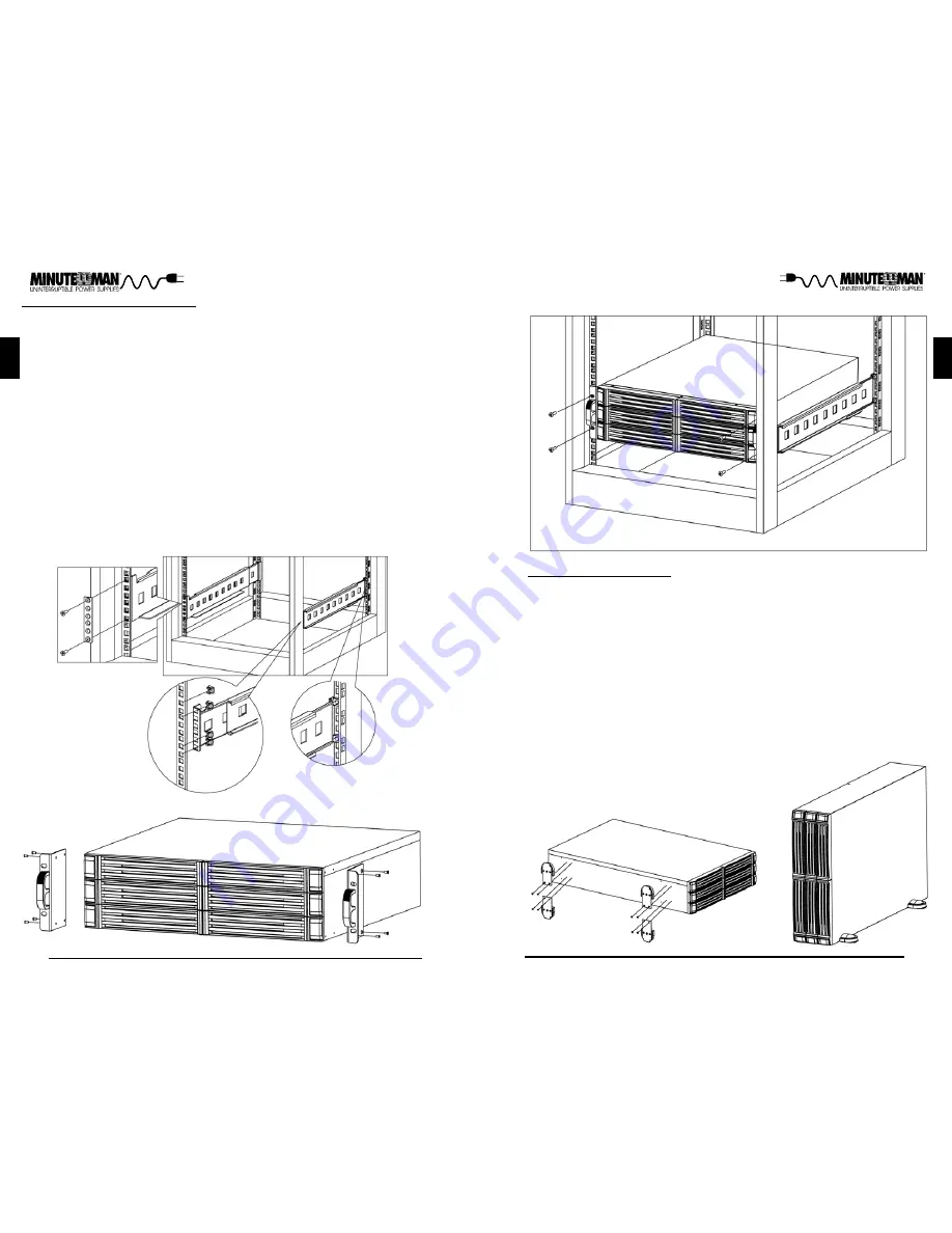
The tower configuration allows the user to install the Battery Pack in the up-
right position next to the UPS. The tower brackets are provided with the Bat-
tery Pack. WARNING: Use two or more people when installing the Battery
Pack. Use CAUTION, the Battery Pack is extremely heavy.
1. Once the location of the Battery Pack has been determined, lay the Battery
Pack on its side. (FIG. 1)
2. Attached the tower brackets to the Battery Pack with the retaining screws.
(FIG. 1)
3. Rotate the Battery Pack to the up-right position. Ensure the Battery Pack
is stable. (FIG. 2)
4. The Tower Configuration is complete. See Connecting the Battery Pack.
English
RACKMOUNT CONFIGURATION
The Battery Pack comes with mounting brackets and rails for the standard 19"
(46.5cm) 4-post rack. The screws for mounting the Battery Pack to the rack
are not included (screw size varies with rack size).
1. Mount the rails to the 4-post rack. (FIG. 1)
2. Locate the mounting bracket screw holes on the side panels of the Battery
Pack, at the front of the Battery Pack. (FIG. 2)
3. Align the mounting bracket with the mounting bracket screw holes. (FIG. 2)
4. Attach the mounting bracket with the retaining screws. (FIG. 2)
5. Install the Battery Pack onto the Rails and secure the Battery Pack to the
rack with the retaining screws. (FIG. 3) WARNING: Use two or more people
when installing the Battery Pack. Use CAUTION, the Battery Pack is ex-
tremely heavy. Do not move the rack after the units have been installed.
The rack maybe unstable due to the weight distribution.
6. The Rackmount Configuration is complete. See Connecting the Battery
Pack.
FIG. 1
FIG. 2
FIG. 3
FIG. 1
FIG. 2


