13
Installation
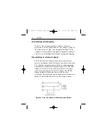
Voltage follower connection
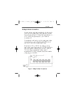
Instead of using a speed adjust potentiometer, the drive may be
wired to follow an analog input voltage signal that is isolated
from earth ground (Figure 5). Connect the signal reference (+)
to S2. Connect the signal common (–) to S1. Make no
connection to S3.
A potentiometer can be used to scale the analog input voltage.
An interface device, such as Minarik model PCM4, may be
used to scale and isolate an analog input voltage.
With either 115 VAC or 230 VAC line voltage, an analog
input voltage range of approximately 0–1.4 VDC is required to
produce an armature voltage range of 0–90 VDC. With 230
VAC line voltage, an analog input voltage range of
approximately 0–2.8 VDC is required to produce an armature
voltage range of 0–180 VDC.
Figure 5. Voltage Follower Connections
250-0089r3_readers_spreads.qxd 7/3/01 10:48 AM Page 13
Содержание MM20000 Series
Страница 8: ...vi MM20000 Series Numbering System 250 0089r3_readers_spreads qxd 7 3 01 10 47 AM Page vi...
Страница 10: ...2 Figure 1 Dimensions Dimensions 250 0089r3_readers_spreads qxd 7 3 01 10 48 AM Page 2...
Страница 27: ...19 Operation Figure 8 Dynamic Brake Connection 250 0089r3_readers_spreads qxd 7 3 01 10 48 AM Page 19...


