background image

Specifications

Max.

Max.

Input

Input

Armature

Voltage

Current

Current

HP

Model

(AC) (Amps AC) (Amps DC)

Range

Style

MM21000A

115

3

5*

1/8 – 1/2*

Chassis

MM21001A

115

3

5*

1/8 – 1/2*

Chassis

MM21010A

115

3

1.5

1/20 – 1/8

Chassis

MM21011A

115

3

1.5

1/20 – 1/8

Chassis

MM22000A

230

3

5**

1/4 – 1**

Chassis

MM22001A

230

3

5**

1/4 – 1**

Chassis

*Max HP = 1 and max armature current = 10A if mounted on 223-0159 heat

sink.

**Max HP = 2 and max armature current = 10A if mounted on 223-0159 heat

sink.

AC Line Voltage Tolerance

±10%, 50/60 Hz, single phase

Armature Voltage

115 VAC line voltage

0 – 90 VDC

230 VAC line voltage

0 – 180 VDC

Field Voltage (1 ADC max)

50 – 100 VDC

Maximum Output Field Current

1 ADC

Form Factor

1.37 at base speed

Accel. Time Range

0.5 – 11 seconds

Decel. Time Range

coast to a stop – 13 seconds

Analog Input Voltage Range (signal must be isolated; S1 to S2)

0 – 90 VDC Motors

0 – 1.4 VDC

0 – 180 VDC Motors

0 – 2.8 VDC

Input Impedance (S1 to S2)

100K ohms

Load Regulation

1% base speed or better

Vibration

0.5G max (0 – 50 Hz)

0.1G max (>50 Hz)

Ambient Temp. Range

10°C – 55°C

1

250-0089r3_readers_spreads.qxd  7/3/01  10:47 AM  Page 1

Содержание MM20000 Series

Страница 1: ...SCR Adjustable Speed Drives for DC Brush Motors User s Manual MM20000 Series Models MM21000A MM21001A MM21010A MM21011A MM22000A MM22001A MM22011A 250 0089r3_readers_spreads qxd 7 3 01 10 47 AM Page a...

Страница 2: ...oration and its Divisions make no warranty of any kind with respect to this material including but not limited to the implied warranties of its merchantability and fitness for a given purpose Minarik...

Страница 3: ...ck or explosion by proper grounding over current protection thermal protection and enclosure Follow sound maintenance procedures It is possible for a drive to run at full speed as a result of a compon...

Страница 4: ...10 Voltage follower connection 13 Operation 14 Before applying power 14 Drive startup and shutdown 14 To shut down the drive 15 Reversing 15 Starting and Stopping Methods 15 Line starting and stopping...

Страница 5: ...le speeds 31 Adjustable speeds using potentiometers in series 32 Multiple fixed speeds 33 RUN JOG switch 34 Leader follower application 35 Single speed potentiometer control of multiple drives 36 Trou...

Страница 6: ...ayout 21 Figure 10 Typical IR COMP and TORQUE Settings 27 Figure 11 FWD STOP REV Switch 28 Figure 12 Reversing Circuit Connection 29 Figure 13 Reversing with a DLC600 30 Figure 14 Independent Adjustab...

Страница 7: ...8 Table 2 Field Output Connections 11 Table 3 Recommended Dynamic Brake Resistor Sizes 18 Table 4 Replacement Parts 41 Table 5 Corcom Filters 44 Table 6 Minarik Filters 45 v Tables 250 0089r3_readers...

Страница 8: ...vi MM20000 Series Numbering System 250 0089r3_readers_spreads qxd 7 3 01 10 47 AM Page vi...

Страница 9: ...0159 heat sink AC Line Voltage Tolerance 10 50 60 Hz single phase Armature Voltage 115 VAC line voltage 0 90 VDC 230 VAC line voltage 0 180 VDC Field Voltage 1 ADC max 50 100 VDC Maximum Output Field...

Страница 10: ...2 Figure 1 Dimensions Dimensions 250 0089r3_readers_spreads qxd 7 3 01 10 48 AM Page 2...

Страница 11: ...3 Dimensions Figure 2 223 0159 Heat Sink Dimensions ALL DIMENSIONS IN INCHES MILLIMETERS 250 0089r3_readers_spreads qxd 7 3 01 10 48 AM Page 3...

Страница 12: ...face and to reach bare metal Drive components are sensitive to electrostatic fields Avoid direct contact with the circuit board Hold drive by the chassis only Protect the drive from dirt moisture and...

Страница 13: ...injury or fatality avoid direct contact with the printed circuit board or with circuit elements Do not disconnect any of the motor leads from the drive unless power is removed or the drive is disable...

Страница 14: ...the user should twist all logic leads with themselves to minimize induced noise It may be necessary to earth ground the shielded cable If noise is produced by devices other than the drive ground the s...

Страница 15: ...ith the hardware provided Twist the speed adjust potentiometer wires to avoid picking up unwanted electrical noise Figure 3 Speed Adjust Potentiometer Installation Warning Be sure that the potentiomet...

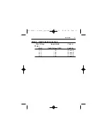
Страница 16: ...ection Use fast acting fuses rated for 250 VAC or higher Table 1 lists the recommended line fuse sizes Table 1 Replacement Line Fuse Sizes 90 VDC Motor 180 VDC Max DC Armature AC Line Fuse Horsepower...

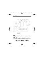
Страница 17: ...cuit board PCB as shown in Figure 4 page 12 Motor connections Minarik drives supply motor voltage from A1 and A2 terminals It is assumed throughout this manual that when A1 is positive with respect to...

Страница 18: ...line fuse between the stop switch if installed and the L1 terminal as shown in Figure 4 on page 12 An additional line fuse should be installed on L2 if the input voltage is 230 VAC The line fuse s sho...

Страница 19: ...2 Field Output Connections Line Voltage Approximate Connec Motor VAC Field Voltage VDC Field To 115 50 F1 and L1 115 100 F1 and F2 230 100 F1 and L1 230 200 F1 and F2 250 0089r3_readers_spreads qxd 7...

Страница 20: ...ctions NOTES 1 DO NOT CONNECT FIELD OUTPUT IF USING A PERMANENT MAGNET MOTOR REFER TO TABLE 2 PAGE 11 FOR ALTERNATE FIELD CONNECTIONS 2 DO NOT ADD A LINE FUSE TO L2 UNLESS LINE VOLTAGE IS 230 VAC 250...

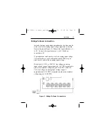
Страница 21: ...he analog input voltage An interface device such as Minarik model PCM4 may be used to scale and isolate an analog input voltage With either 115 VAC or 230 VAC line voltage an analog input voltage rang...

Страница 22: ...ference signal or speed adjust potentiometer to minimum speed 2 Apply AC line voltage 3 Slowly turn the speed adjust potentiometer or increase the reference voltage until the desired speed is reached...

Страница 23: ...tion of an emergency stop switch for chassis drives The switch contacts should be rated at a minimum of 250 volts and 200 of maximum motor current To shut down the drive To decelerate the motor from s...

Страница 24: ...may be used to decelerate a motor to a minimum speed Closing the switch between S1 and S2 decelerates the motor from set speed to a minimum speed determined by the MIN SPD trimpot setting If the MIN...

Страница 25: ...shielded cable if the inhibit wires are longer than 18 inches 46 cm If shielded cable is used ground only one end of the shield to earth ground Do not ground both ends of the shield Minarik Corporatio...

Страница 26: ...resistor with 12 gauge wire Dynamic braking may be used to rapidly stop a motor Figure 8 For the RUN BRAKE switch use a double pole double throw switch rated for at least the maximum DC armature volt...

Страница 27: ...19 Operation Figure 8 Dynamic Brake Connection 250 0089r3_readers_spreads qxd 7 3 01 10 48 AM Page 19...

Страница 28: ...ious or fatal injury MM21xx1A and MM22xx1A Series drives have six user adjustable trimpots Each drive is factory calibrated to its maximum current rating Readjust the calibration trimpot settings to a...

Страница 29: ...21 Calibration Figure 9 Calibration Trimpot Layout DECELERATION ACCELERATION MINIMUM SPEED REGULATION IR COMP MAXIMUM SPEED TORQUE LIMIT 250 0089r3_readers_spreads qxd 7 3 01 10 48 AM Page 21...

Страница 30: ...nal or speed adjust potentiometer to zero 5 Apply power to the drive 6 Calibrate the trimpots as follows MINIMUM SPEED MIN SPD The MIN SPD setting determines the motor speed when the speed adjust pote...

Страница 31: ...1 for approximate acceleration times ACCEL is factory set for the fastest acceleration time full CCW To set the acceleration time 1 Set the speed adjust potentiometer or reference signal to minimum T...

Страница 32: ...ce signal to maximum The motor should run at maximum speed 2 Set the speed adjust potentiometer or reference signal to minimum and measure the time it takes the motor to go from maximum to minimum spe...

Страница 33: ...d to measure motor speed 3 Load the motor armature to its full load armature current rating The motor should slow down 4 While keeping the load on the motor rotate the IR COMP trimpot until the motor...

Страница 34: ...eed potentiometer or reference signal to maximum speed The motor should remain stopped 6 Slowly rotate the TORQUE trimpot clockwise CW until the ammeter reads 120 of maximum motor armature current 7 S...

Страница 35: ...27 Calibration Figure 10 Typical IR COMP and TORQUE Settings settings may vary by application 250 0089r3_readers_spreads qxd 7 3 01 10 48 AM Page 27...

Страница 36: ...t the switch to the center position to decelerate the motor to a stop The switch contacts should be rated at a minimum of 250 volts and 150 to 200 of motor nameplate current Wait for the motor to come...

Страница 37: ...re 12 Use a three pole three position switch rated for at least the maximum DC armature voltage and maximum braking current Wait for the motor to stop completely before switching it to either the forw...

Страница 38: ...while braking Without the inhibit feature the controller will continue to regulate causing overshoot when the DIGI LOK is switched back to the drive Figure 13 shows the connection of the reversing ci...

Страница 39: ...h a single pole two position switch to select between two independent speeds shown in the forward direction Figure 14 The speed adjust potentiometers can be mounted at two separate operating stations...

Страница 40: ...ingle pole multi position switch and two or more potentiometers in series with a total series resistance of 10K ohms Figure 15 shows a connection for fixed high and low speed adjust potentiometers Fig...

Страница 41: ...r with series resistors with a total series resistance of 10K ohms Figure 16 Add a single pole multi position switch with the correct number of positions for the desired number of fixed speeds Figure...

Страница 42: ...OG switch and a single pole normally closed momentary operated pushbutton for the JOG pushbutton as shown in Figure 17 When the RUN JOG switch is set to JOG the motor decelerates to zero speed Press t...

Страница 43: ...motor from the follower drive and outputs a voltage proportional to the leader motor armature voltage The follower drive uses this voltage reference to set the speed of the follower motor An optional...

Страница 44: ...adjust potentiometer using a PCM4 at the input of each drive to provide isolation Figure 19 Optional ratio potentiometers can be used to scale the PCM4 output voltage allowing independent control of e...

Страница 45: ...in good condition Verify that there are no short circuits or grounded connections Check that the drive s rated armature outputs are consistent with the motor ratings For additional assistance contact...

Страница 46: ...size 2 Check motor cable and armature for shorts 3 Add a blower to cool the drive components decrease TORQUE settings or resize motor and drive for actual load demand or check for incorrectly aligned...

Страница 47: ...shunt wound motors only MIN SPD and MAX SPD are not calibrated 1 MAX SPD setting is too low 2 IR COMP setting is too low 3 Motor is overloaded 3 Verify that the motor is not jammed Increase TORQUE se...

Страница 48: ...under load 1 IR COMP is set too high 2 Control is in current limit mode 1 Adjust the IR COMP setting slightly CCW until the motor speed stabilizes page 25 2 Check that motor is of sufficient horsepow...

Страница 49: ...wer SCR 072 0043 R501 0 05 Ohm 3W Resistor 032 0073 T501 ST 3 3109 Transformer 230 0083 Chassis 222 0079 10K Ohm Pot Kit 202 0031 MM22001A Same as MM21011A except R501 0 01 Ohm 5W Resistor 032 0129 20...

Страница 50: ...3AG FAST ACTING FUSE 050 0021 2 EA 5 AMP 3AG FAST ACTING FUSE 050 0022 5 15A FUSE KIT 050 0071 Description Minarik P N 2 EA 5 AMP 3AG FAST ACTING FUSE 050 0022 2 EA 8 AMP 3AG FAST ACTING FUSE 050 0059...

Страница 51: ...1 emissions and EN50082 1 1992 immunity Compliance allows Minarik s MM21000 series to bear the CE mark The end user as described herein falls into one of two categories 1 The Consumer will deploy a st...

Страница 52: ...s Rated current 1 4 times maximum DC motor current Filter type Balanced 2 section Table 5 Corcom Filters Nameplate Current of Motor Wired to the Drive Corcom Filter Part Number 0 to 4 amps 6VV1 4 1 to...

Страница 53: ...ailable the specifications are as follows L L1 2 0 8 milliHenries C C1 2 0 1 microFarads 400W VDC Rin 0 1 ohm Rout 1 2 ohm Table 6 Minarik Filters Nameplate Current of Motor Wired to the Drive Minarik...

Страница 54: ...achine for CE approval Thus no component must necessarily meet CE within the machine as long as the OEM takes the necessary steps to guarantee the machine does meet CE By the same token even if every...

Страница 55: ...In the event of any claim for breach of any of the Corporation s obligations whether express or implied and particularly of any other claim or breech of warranty contained in Paragraph A or of any oth...

Страница 56: ...0 394 6334 www minarikcorp com Document Number 250 0089 Revision 3 Printed in the U S A 6 01 12 00 North America 13 00 Outside North America DLC600 BOSS Series MMRGD Series NRGD Series Other drives fr...

Отзывы: