background image

– 1.13 –

Connecting the cables

* When connecting the cables, turn off first the power to the device and that to

the host computer which the power cable is to be connected.

* Do not insert/remove the cable during data transferring.

* Follow the instructions in case the wizard displayed when connected a USB cable.

Connecting USB Driver

As for USB driver connection, refer to "USB Driver Installation Guide" in the supplied FineCut.

1. Set the CD supplied with FineCut into the disk drive.

2. Click [CD-ROM Contents] on the menu.

3. Open [usb11_installguid(en).pdf] for the plotter used in [Mimki USB1.1 Driver] folder.

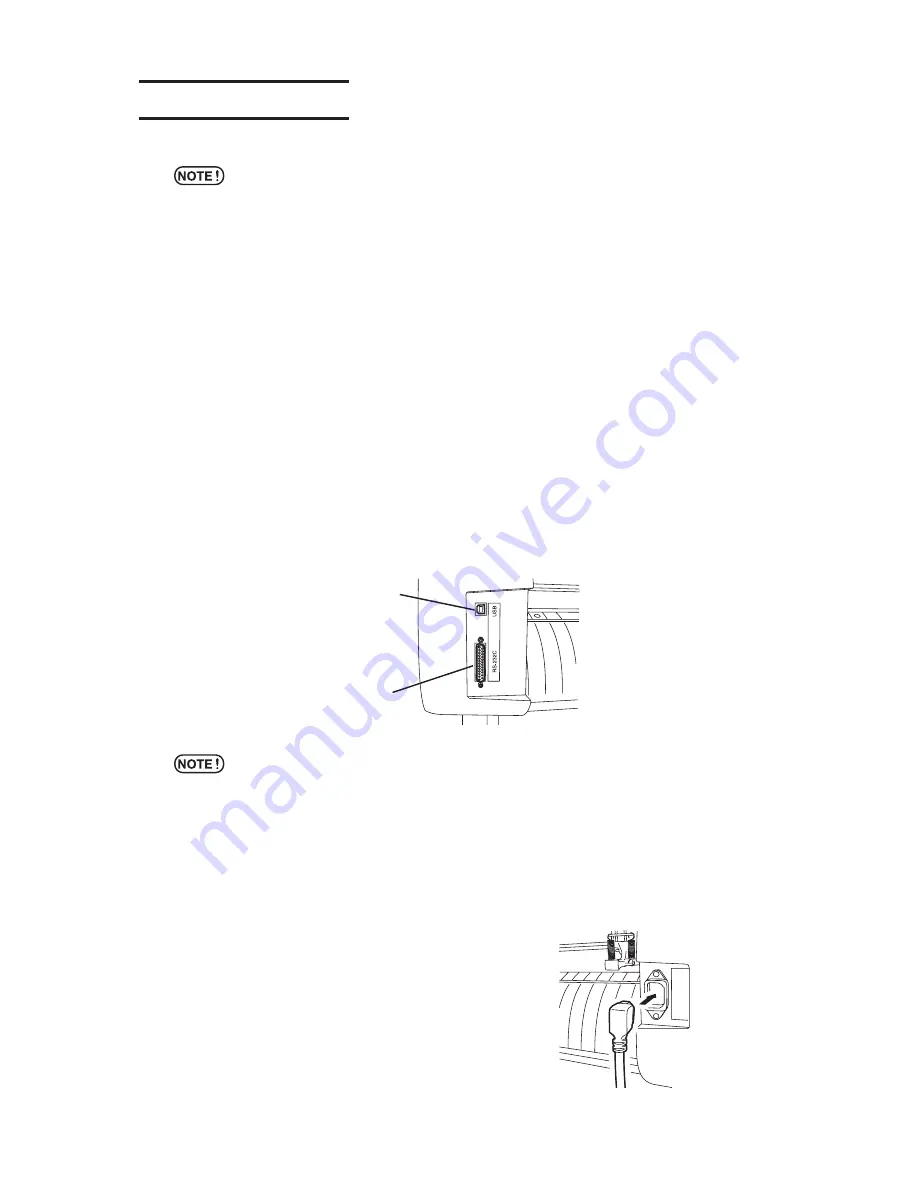
Connecting the interface cables

The device comes with two different kinds of interfaces.

Select either one that matches the host computer.

RS-232C compatible interface

USB interface

* It is necessary the settings of interface which to use.

* Plug in/out the connecter carefully.  Too much pressure may damage the

connecter.

Connecting the power cables

After the completion of interface cable connection, connect the power cable.

Connect the power cable to the receptacle of the following power specification.

Voltage

AC100V to 240V 

±

10%

Frequency

50/60Hz 

±

1%

Capacity

100W or more (equivalent to 2 A)

USB interface

RS-232C
compatible interface

Содержание CG-130FXII

Страница 1: ...D201812 12 OPERATION MANUAL MIMAKI ENGINEERING CO LTD URL http www mimaki co jp CUTTING PLOTTER CG FXII Series...

Страница 2: ......

Страница 3: ...L MIMAKI BE LIABLE FOR SPECIAL INCIDENTAL OR CONSEQUENTIAL DAMAGES OR FOR LOSS OF PROFITS OF DEALER OR CUSTOMERS OF ANY PRODUCT Requests This Operation manual has been carefully prepared for your easy...

Страница 4: ...to the television set or radio FCC Statement USA This equipment has been tested and found to comply with the limits for a Class A digital device pursuant to Part 15 of the FCC Rules These limits are d...

Страница 5: ...evice Please read and fully understand this Operation manual before putting the machine into service It is also necessary to keep this Operation manual on hand Make arrangements to deliver this Operat...

Страница 6: ...ode substantially increases the clamp pressure that prevents a long sheet slippage The moderate pressure mode prevents from getting scratching by grit roller during plot operation New Cutter Holder Th...

Страница 7: ...ol indicates helpful information that will facilitate the use of the device Indicates the reference page for related contents Example of pictorial signs 2 The symbol indicates the case where some phen...

Страница 8: ...power cable Use the supplied power cable Take care not to damage break or work on the power cable If a heavy matter is placed on the power cable heated or drawn the power cable can break to cause fire...

Страница 9: ...hich temperature and humidity vary by a great margin Use the device under the following environment Operating environment 20 to 35 C 35 to 65 Rh A place exposed to direct air blow from air conditioner...

Страница 10: ...t is likely to tightly curl flatten first the paper before using it for printing Heavily curled sheet affect the Cut plotted result Caution with cutters Do not touch the edged cutter blade Do not swin...

Страница 11: ...informs the customer of possible risks associated with the device Be sure to understand the correct meaning of the safety label to avoid danger If the safety label is illegible due to stains or has co...

Страница 12: ...4 The Rear 1 5 Operation Panel 1 6 Carriage 1 8 Pinch rollers and grit rollers 1 8 Control the clamp pressure 1 10 The sheet sensor 1 11 Pen line 1 11 Scale seal 1 12 Connecting the cables 1 13 Menu...

Страница 13: ...ta DATA CLEAR 3 12 Modify the sheet displacement ENTER HOLD 3 13 Enter the registration mark detection mode END 3 13 Functions 3 14 Test cutting SQUARE CUT 3 16 Cut plot the same data on multiple shee...

Страница 14: ...ET sensor 3 68 Set the movement speed of carriage and sheet UP SPEED 3 69 Set the movement distance of carriage and sheet JOG STEP 3 69 Mute setting on the key noise and the error buzzer BUZZER 3 70 S...

Страница 15: ...el Display panel The content of display is shown in characters in a box as shown at right Operate the device according to the explanation of the operation procedure and the content of display on the L...

Страница 16: ...xiv...

Страница 17: ...ore Use This chapter describes on the parts name and setting procedures before use Table of contents Checking the accessories 1 2 Configuration and function 1 4 Scale seal 1 12 Connecting the cables 1...

Страница 18: ...asuring a leaf sheet Roll bar 2 Roll assist bar 1 Roll holder 2 Stay 2 Roll stay Assembly 2 Power cable 1 Operation Manual 1 CD ROM 1 FineCut USB Driver Product name Q ty Remarks Checking the accessor...

Страница 19: ...n Main unit BOX Cutter holder Cap Roll stay Assembly Power cable Scale seal Cable clamp Roll holder Roll bar 2 pieces Roll assist bar 1 pieces Stay Operation Manual CD ROM USB Driver FineCut Cutter bl...

Страница 20: ...ctions are set on the operation panel Page 1 6 6 Clamp lever Tilting the lever away from you lowers the pinch rollers to retain the sheet of medium 7 Pen line rubber The device performs cutting or plo...

Страница 21: ...he turn back lever works to prevent the lower roll sheet from coming in contact with the upper roll sheet 6 RS 232C interface The RS 232C compatible interface connector connector It is connected to th...

Страница 22: ...6 END key It is used to cancel the value is last previously input Use the key to detect only the sheet width 7 ENTER HOLD key This key is used to enter the last previous input value for a setup item U...

Страница 23: ...e top end of the sheet In the case where a roll sheet is loaded onto the front of the device Detects the width and length of the sheet In the case where a cut sheet is loaded onto the front of the dev...

Страница 24: ...rs in accordance with the width of sheet to be loaded on the device The areas within which the pinch rollers may be shifted are described below Change the location of the pinch rollers using the PINCH...

Страница 25: ...eftmost end of its travel range in the case where the pinch roller 3 is not used for operation Or set to the number of pinch roller its using Page 3 70 If the pinch roller 3 is located at any position...

Страница 26: ...iddle clamp in need See below CG 75FXII CG 130FXII CG 160FXII High mode Raise the clamp pressure lever Low mode Lower the clamp pressure lever Clamp pressure Application High mode For cutting the shee...

Страница 27: ...and plotting The sponge pen line is used for pouncing and cutting on dotted line Use the appropriate pen line depends on the tool attached position The sheet sensor The sheet sensors detects the prese...

Страница 28: ...he scale seals mm unit scale seal and the inch unit scale seal Put a scale seal on a main unit 1 Remove the seal little by little from the end to put on the main unit Put the seal on the platen as sho...

Страница 29: ...Open usb11_installguid en pdf for the plotter used in Mimki USB1 1 Driver folder Connecting the interface cables The device comes with two different kinds of interfaces Select either one that matches...

Страница 30: ...he appropriate JOG keys to detect a sheet and set up an origin 2 Pushing the TOOL key to select a tool and set the configurations 3 Pushing the DATA CLEAR key to erase the cutting plotting data the de...

Страница 31: ...e Make sure not to turn off power during displaying the following message In the case setting values cannot be saved normally all the values return to default values at the factory F ROM WRINTING Tabl...

Страница 32: ...from power on to end of cutting plotting For details on each item refer to the reference page Tool P 2 3 Turn on the power on P 2 7 Set the tool conditions P 2 8 Set the sheet P 2 13 Execute test cutt...

Страница 33: ...changing the cutter blade or procedure of adjust ing the other cutter blade Refer to Page 5 4 How to attach a cutter blade 1 Loosen the cutter holder cap 2 Insert the cutter blade into the cutter hold...

Страница 34: ...b to the right The blade tip comes out 0 5mm for a circle Protruding amount of the cutter blade Film thickness Base paper thickness 1 2 1 Film thickness Base paper thickness Protruding amount of the c...

Страница 35: ...the tool holder at a time If the device performs cutting on this side sponge an adequate pressure will not be applied to the sheet of media adversely affecting the cutting result The device is not abl...

Страница 36: ...gauge With level or bumps 1 Put the cap on the pen adapter Use the cap to adjust a pen height 2 Insert the pen into the pen adapter Insert the pen all the way until the pen tip hits the cap 3 Fix the...

Страница 37: ...llowed the device can malfunction 1 Press the side of the power switch When the device is turned on the device will enter operation modes in the predetermined order Refer to page 1 14 for the operatio...

Страница 38: ...nder the high cutting pressure the abnormal noise may occur and the surface of the sheet may be damaged resulting inferior cutting quality CT1 020 050 0 30 CT2 020 080 0 30 CT3 050 150 0 30 CT4 020 06...

Страница 39: ...of media OFFSET The amount of the cutter blade tip from Center of the holder If the offset amount is increased square shaped characters will be cut plotted If it is decreased round edged characters w...

Страница 40: ...maximum at 60cm s In case setting a cut line segment at 1000mm and above the cutting speed is limited maximum at 60cm s Procedure 1 Press TOOL key to select the cut number Select CT2 2 Change the spee...

Страница 41: ...ng a sheet of media conduct test plotting to check the quality of finished characters and marks Type of pen SPEED PRESSURE Water ink ball point pen 0 3 mm 40 cm s 60 g Oil based ink ball point pen 40...

Страница 42: ...ess Cutting pressure to remain after cutting Half cut length Length of sheet to remain after cutting Cut length Length by which the sheet is cut out Setting value SPEED 1 to 10 cm s 1 cm s step 15 20...

Страница 43: ...t Enable to load of the Sheet width mm inch CG 75FXII 90 to 1040 24 30 36 40 CG 130FXII 90 to 1580 24 30 36 42 48 50 52 60 62 CG 160FXII 90 to 1880 24 30 36 42 48 50 52 60 62 Maximum cutting area The...

Страница 44: ...as with the case where the END key is pressed The setting direction of the media is rendered effective The maximum length that can be detected at the front and rear ends of the sheet of media is 3 m M...

Страница 45: ...the sheet detection Key Detecting method Example of display after the sheet detection Only the sheet width is detected A B In the case where the detected dimension is 3 m or more the display will appe...

Страница 46: ...lever away from you and lower the pinch rollers The display shown on the display panel will change as illustrated below 4 Press the jog key or to select LEAF In the case where the media is loaded fro...

Страница 47: ...in the slit 2 and 3 2 Load a roll sheet Place a roll sheet on the roll bar pass the top end of the sheet through the platen and change the location of the pinch rollers according to the sheet width C...

Страница 48: ...ard you from the front side of the main unit If you don t release the roll stopper the device stop with buzzer during sheet feeding 7 The display shown on the LCD changes Press the jogkey or to select...

Страница 49: ...ss FUNCTION key 3 Select SQUARE CUT and press ENTER HOLD key Execute test cutting plotting Back to the local mode after plotting Reset the cut configurations according to the test cutting plotting res...

Страница 50: ...data to be cut plotted To start cutting plotting be sure to specify an origin in prior Reset the origin point before performing the subsequent data cutting to prevent from cutting on the previous cut...

Страница 51: ...otting press the REMOTE key once Another press on the same key will allow the device to resume cutting plotting If any function that initiates some action or any operation that can affect the command...

Страница 52: ...power off check first whether or not there is data received 1 Confirm not receiving any data Confirm the display indicates the remote mode or the local mode Leave 5 seconds and more intervals before t...

Страница 53: ...the functions invoked with the jog key functions invoked with specific keys and other functions Table of contents Functions invoked with the jog mode jog keys 3 2 Functions invoked with the specific...

Страница 54: ...ration refer to Appendix Page 5 11 CT1 020 050 0 30 0 0 0 0 ORIGIN PAPER CUT ENT 0 0 0 0 p 0 0 0 0 A B PAPER CUT COMP A B CUT AREA Local mode Jog mode FUNCTION Origin Page 2 20 Paper cut Page 3 4 Two...

Страница 55: ...ect parameters to determine the setting Select parameters for the functions origin point setting cut area setting and the two point axis alignment setting Use the jog keys to select parameters 5 Regis...

Страница 56: ...h between the pinch roller 1 and the pinch roller 3 as the maximum width the available paper cut range is as follows 40mm from the inside of the pinch roller 1 80mm form the inside of the pinch roller...

Страница 57: ...is the effective cutting area If you tilt the clamp lever toward you the cut area specified will be cleared Be sure to specify an upper left point in the area that is located in the normal direction f...

Страница 58: ...ual for the application software for how to use the digitization function 1 Set the device in the remote mode The device receives the digitization command from the host computer The display on the LCD...

Страница 59: ...menu configuration refer to Appendix Page 5 9 CT1 020 050 0 30 CT1 REMOTE DIST COMP ENT DATA CLEAR ENT Local mode Remote mode Dist comp Page 3 9 Sheet feed Page 3 12 Hold function Page 3 13 Tool selec...

Страница 60: ...d Turn off the power supply to return to the toll configuration values REMOTE key is effective after detecting a sheet In case temporarily interrupt cut operation some functions may not be effective w...

Страница 61: ...o the correction values Carefully specify the tool number by commands Find compensation value Compensation value Measurement of the OFF line Reference length input Example Measurement of the OFF line...

Страница 62: ...mum reference length will appear on the LCD The length display shown below means that the DIST COMP was executed using the mark detecting function or the DIST COMP was changed over to the MM INCH A pr...

Страница 63: ...xis Measure the line without a sheet by tilting the clamp lever toward you 13 Perform step1 to step11 Since there is no sheet set the input compensation value screen will be displayed 14 In case the r...

Страница 64: ...gth is shorter than the set value sheet feeding stops as displaying the fed sheet length If this display appears on the LCD press any key to reset it To interrupt the sheet feed press the END key Clea...

Страница 65: ...plotting a line segment of a character the starting point and end point of cutting plotting will not meet When correcting the displacement of the sheet move neither the carriage nor the pinch rollers...

Страница 66: ...ASCII DUMP ENT SHEET CUT ENT DISPLAY ENT FUNCTION FUNCTION FUNCTION FUNCTION FUNCTION FUNCTION FUNCTION FUNCTION Functions This section describes the procedure of switching function menu and the opera...

Страница 67: ...n menu Display functions during each pushing on the FUNCTION key or the jog keys 3 Select a function The following functions perform the operation SQUARE CUT No COPIES SAMPLE CUT LIST ASCII DUMP SHEET...

Страница 68: ...g plotting in repetition on as many as 999 sheets When the device receives new data the data stored in the receiver buffer will be updated Cannot cut the previous data on multiple sheets Setting value...

Страница 69: ...or appears on the LCD refer to Chapter 4 Check the sensor for the registration mark detection MARK sensor Check the sensor Affects to the registration mark detection noise Registration mark condition...

Страница 70: ...key 9 Push ENTER HOLD key after confirming SENSOR CHK is displayed 10 Set the each configurations paper hold ON OFF length of the registration mark shape of the registration mark and speed of the regi...

Страница 71: ...on and contact us 2 Detect operation 2 1 Set the detection speed at 10cm s 2 Scan to the B direction plus direction to detect the line 3 If succeed to detect the line back to the detec tion starting p...

Страница 72: ...ush ENTER HOLD key 6 Select POINTER OFS by pushing jog keys 7 Push ENTER HOLD key The light pointer on and moves to a center of a crisscross pattern to plot a 10mm by 10mm crisscross pattern 8 Adjust...

Страница 73: ...sing the jog key 5 Press the ENTER HOLD key 6 Select SENSOR OFS by pressing the jog key 7 Press the ENTER HOLD key After detecting the register mark one point five additional lines are cut every 0 2 m...

Страница 74: ...mm enter 0 2 9 Press the ENTER HOLD key The plotter will return to the local mode after registering the compensation value The setting values are kept in memory even when the power is turned off The...

Страница 75: ...keys and select magnification of sample data to cut when LOGO is selected You may select within the range of 1 to 999 6 Press ENTER HOLD key to start cutting When sample cut is made the data stored i...

Страница 76: ...this function the device plots tool conditions communication conditions and functions setting conditions for your notes or for facsimile sending at the of maintenance Use a pen as a tool and plot on a...

Страница 77: ...he data received in ASCII format To execute the dump be sure to use a pen as the tool The dump can be executed with the interface to which the host computer is connected To put the dump on hold press...

Страница 78: ...tter is in local mode and then press the FUNCTION key 2 Press the ENTER HOLD key 3 By pressing the jog key or set the number of times cutting is to be performed 4 Press the ENTER HOLD key 5 Set the cu...

Страница 79: ...English Change the language as needed Set each functions SET UP Refer to Page 3 28 N G O K When Front cut off is enabled the leading edge of the sheet is cut at start of SHEETCUT A constant cut lengt...

Страница 80: ...CE ent CUT MODE ent ORGN SELECT ent EXPANDS ent AUTO CUT ent ROTATION ent BUZZER ent DIVISIONcut ent DEVICE No ent MARK DETECT ent COMMAND MGL IIc BAUD RATE 9600 CUT MODE NORMAL LOWERrightORIGIN EXPAN...

Страница 81: ...stration marks There are some limitations on inputting data with registration marks In order to fully utilize this function please read the following datails carefully The registration mark described...

Страница 82: ...e2 30mm and more Cutting Pen plotting 40mm and more Half Cut Pouncing A Between 50 and 9000mm A Between 50 and 9000mm 20mm and more Normal 10mm and more Expand B 50mm and more B 50mm and more Keep the...

Страница 83: ...rrect detection of the origin or marks When the mark origin gets detected incorrectly the cutting area will be altered Mark Form Type1 Mark Form Type2 Example of incorrect detection 1 The plot is outs...

Страница 84: ...tration marks The size of the registration mark in accordance with the distance between marks is as follows When the size is too small the marks will not be detected correctly A 200 max 500 max 1000 m...

Страница 85: ...r 800mm or wider sheet set in 210mm x 297mm to 297mm x 420mm size including four sides of the registration marks It enables to the wasteful margins to place efficiently the image 1 1 Depends on the si...

Страница 86: ...ion mark size to 8mm In case 8mm or shorter registration mark recognized continuously may cause the glitches on the main unit Color of mark The mark shall be printed in black against the white backgro...

Страница 87: ...ior to distance correction in the function If changes the distance correction value the scale correction between the registration marks will be invalid Clear the origin position sheet slope correction...

Страница 88: ...ection OFF The sheet clamps are not used for the mark detection Set to OFF when in use of the thin sheet or prevent from scratching on the sheet If the sheet clamps are not used the clamp detection ma...

Страница 89: ...When the origin becomes out of the effective cutting area ERR37 MARK ORG will be appeared on the display In the cause please write the position of registration marks on the seat on a center side of th...

Страница 90: ...0 cm s Set the speed limit when rapidly moving in performing continuous copy Depends on the sheet type in use mark detect may not be performed correctly if using a slippery sheet In the case set the s...

Страница 91: ...direction In case the TP1 mark misaligned over the range cutting performance is temporally stopped Push on the ENTER key after altering the sheet feeding error Push on the ENTER key after moving the l...

Страница 92: ...t back and forth once Time required for detection is short however the accuracy becomes lower a little PREC After scanning the registration mark segment back and forth once measures the position witho...

Страница 93: ...ated between TP1 and TP2 and in the area B located between TP1 and TP3 Confirm sheet slope by a light pointer Pull clamp lever down and the pinch rollers upholds to light the light pointer The carriag...

Страница 94: ...ing line depends on the tool in use In the case where the PEN or CUT is specified in the tool conditions To the pen line rubber side In the case where the PIN or HALF is specified in the tool conditio...

Страница 95: ...to 1pt the scale correction setting display will not appear but the origin point 6 Push on the ENTER HOLD key after complet ing the settings Start the registration mark detection If any of the marks c...

Страница 96: ...the registration marks the scale correction display appears The right sample shows the 4 points detection display In case the actual measured value and the detected lengths differ set the value with...

Страница 97: ...he sheet and the device will perform the sheet detection 2 Perform the sheet detection by pushing on the jog keys When the sheet is set to the rear position In case ROLL SELECT is set ON select the nu...

Страница 98: ...MARK DETECT its set to 2ptA the display to enter the B length will not appear If MARK DETECT is set to 1pt the scale correction setting display will not appear but the origin point 6 Push on the ENTE...

Страница 99: ...3 47 7 Set the origin After detecting the registration marks the appropriate cutting area will be displayed then local mode will return CT1 020 050 0 30 ORIGIN A B...

Страница 100: ...appears The right sample shows the 4 points detection display In case the actual measured value and the detected lengths differ set the value with the jog keys Push on the ENTER HOLD key to the follow...

Страница 101: ...tting to OFF Procedure 1 Push on the END key to release the registra tion mark detection mode Return to the local mode after displaying the available cutting area 2 Push on the FUNCTION key Enter the...

Страница 102: ...ouncing 10mm 10mm 10mm 20mm In case too strong pressure to the sheet may cause the paper jam when the Expand mode is set to ON In case no axis alignment setting the blade tip protrudes from a sheet ma...

Страница 103: ...s recommended in such a case to select the HIGHspd for smoother finish Set the function according to the blade tip direction DUMMY CUT With this function the device operates in such a way as to orient...

Страница 104: ...utomatic feeding function FEED OFFSET Set the offset value to feed with a little extra When performing the auto feeding function a paper tube may move loudly in case of the roll sheet comes up to the...

Страница 105: ...will happen to cut both side of the edge automatically as follow it is narrower value of cutting point than setting value of Mark detection Paper scale is over more than normal prevend from cutting p...

Страница 106: ...he three steps cutting the cut part may be roughly and some paper chips may be generated When performing the two steps cutting for a wider or heavier sheet the correct cutting may not be performed for...

Страница 107: ...the frame cutting or adhesion allowance marking the device will perform cutting based on the size of data on cutting If the host computer designates the frame cutting and sends data to the device the...

Страница 108: ...e following display will appear on the LCD panel Setting value DIVISION CUT ON OFF FRAME CUT ON OFF MARK CUT ON OFF Procedure 1 Set the DIVISIONcut to the ON state 2 Send data from the host computer t...

Страница 109: ...et has no space for cutting replace the sheet with a new one 6 Press the REMOTE key to set the device in the remote mode Feed the sheet by the maximum sheet length required by data on cutting and star...

Страница 110: ...ill be shorter than that of the one used for normal cutting Setting value Half cut Setting of broken line cutting ON OFF Half cut press Cutting pressure of sheet to remain after cutting 0 g to 80 g Ha...

Страница 111: ...etc In order to create perforated pattern pin pouncing tool and use a paper sheet but a vinyl sheet Setting of the cutting conditions PIN Setting value OFF The pouncing function is rendered ineffecti...

Страница 112: ...in use the LOWER right ORIGIN is set Setting value CENTER ORIGIN Center of the available cutting area LOWER right ORIGIN Lower right of the available cutting area Lower right origin of the A B coordi...

Страница 113: ...tion the carriage will stop at the origin Axis of coordinates The device has four different axis of coordinates according to how the sheet loading direction and the angle of rotation of the coordinate...

Страница 114: ...the automatic sheet feed function The automatic sheet feed function enables to feed the required length of the sheet beforehand When the sorting is effective a block of data from the starting point of...

Страница 115: ...display 4 Set the sorting to ON or OFF by pushing on the jog keys Push on the ENTER HOLD key to display the AREA func tions 5 Set the AREA functions by pushing on the jog keys Set the value in between...

Страница 116: ...gth of data to be cut If the sheet is not long enough to cover the whole data the error shown below is displayed After changing to a long sheet transmit data or execute No COPIES Refer to Page 3 16 4...

Страница 117: ...large data the AUTO mode may not function normally In that case change the command to the specific command MGL Ic1 or MGL IIc When the value is set to AUTO in receiving a data from a computer the dis...

Страница 118: ...IIc 0 025 0 01 mm MGL Ic1 0 05 0 1 mm Close time 1 3 to 60 sec 1 Close time The minimum waiting time is required until the subsequent data is received The setting range is 3 to 60 seconds If no data i...

Страница 119: ...ting command AS Pen pressure setting command FS ZF Blade tip correction setting command ZO Setting value PANEL The device operates using the setting established on its operation panel HOST The device...

Страница 120: ...from the sheet sensor The sheet of which wrong side is black that does not reflect the light coming from the sheet sensor In this case cutting is enabled by setting the SHEET SENSOR function contained...

Страница 121: ...SPEED setting will be 10 cm s Set the movement distance of carriage and sheet JOG STEP This function is used to select the amount of travel of the carriage and sheet when the jog key arrow key is pre...

Страница 122: ...e uncut parts on the starting point and the end point increase the value Due to the low pressure on the cutter blade some parts remain uncut When using a slant blade supplied as an option some corner...

Страница 123: ...H ROLL Set the number f pinch roller to detect when the sheet detection Set the ROLL SELECTION is ON enable to select the number of pinch roller when sheet detection Setting value PINCH ROLL 2 3 CG 75...

Страница 124: ...the potion front by the specified length and then stops at the position back by the length Setting value OFF 0 1 to 1 0mm by 0 1mm The cutting remainder at the start and end position specially for fle...

Страница 125: ...ODE Set the mode after detecting the sheet Setting value LCL The mode switches to the standby condition of the local mode after detecting the sheet REM The mode automatically switches to the remote mo...

Страница 126: ...f intervals of the registration mark size Then when it finds a segment a point or a printed material the registration mark detection will be performed If the vertical line and the horizontal line are...

Страница 127: ...END key twice to return to the local mode If it is not recognized as a registration mark or there is no response even if the fuction scans the area set for search the message indicating the search fa...

Страница 128: ...NCTION key 3 Select SET UP by pushing the jog keys 4 Push on the ENTER HOLD key 5 Select SETUP RESET by pushing the jog keys 6 Push on the ENTER HOLD key Initialize the setting items and the parameter...

Страница 129: ...1 CHAPTER 4 In Case Of Trouble This chapter describes on the actions on the errors Table of contents Before taking a phenomenon as a trouble 4 2 Trouble for which error messages are given on the LCD 4...

Страница 130: ...rn on the power to the device An error arises on the device when the host computer sends data to the device Communication conditions have not been properly established Check up the communication condi...

Страница 131: ...s to be cut longer be sure to secure a sufficient space for working in the direc tion to which the sheet is fed Front 1 5 m or more Back 1 5 m or more The device drags the tool during running The shee...

Страница 132: ...ision cut the device has failed to feed the sheet according to the second data by the length specified by the first data Load a longer sheet on the device and re set the device in the remote mode Erro...

Страница 133: ...ation mark settings Confirm the status and the settings described above If still no registration mark detected contact your distributor or us ERR32 DATAtooBIG The amount of received data is too large...

Страница 134: ...sing the jog keys ERR42 A CURRENT An overcurrent error in the motor in the lengthwise direction of the sheet has been detected ERR43 B CURRENT An overcurrent error in the motor in the widthwise direct...

Страница 135: ...ost computer to enter the local mode Execute required operations such as the sheet detection or the establishment of an origin Then press the REMOTE key to make the device to enter the remote mode DIG...

Страница 136: ...his message appears in the following cases In the case where the device has received data that contains the origin updating command ZT PG In the case where the sheet width is 1 cm or less In the case...

Страница 137: ...s Specifications of the main unit 5 2 Repeatability condition 5 3 Cutter blade 5 4 Replacing the cutter blade 5 4 Adjusting the cutter blade 5 5 How to replace the blade for sheet cutter 5 6 Sheet set...

Страница 138: ...r ink ball point pens oil ink ball point pens Commercial product for a boll point pen 8 Commands 9 MGL IIc MGL Ic1 Interface RS 232C USB Receiver buffer 30 MB standard 20Mb when the sorting function i...

Страница 139: ...sing the sheet feeding function A roll sheet shall not slacken No difference in height shall be observed between the right and left end faces Cutting speed 40 cm s or less when the cutter supplied wit...

Страница 140: ...blunt replace it with a new one New blades low pressure blade set for PVC sheet Model SPB 0030 are available from your distributor MIMAKI sales office Replacing the blade of the cutter supplied with t...

Страница 141: ...th the unit 1 Loosen the locknut 2 Turn the adjusting knob to adjust the protrud ing amount of the blade 3 Tighten the locknut to secure the adjusting knob Film Base paper Protruding amount of the cut...

Страница 142: ...tter blade under your district low Procedure of replacing the blade for sheet cutter 1 Loosen the screws of the blade for sheet cut ter 2 Remove the blade 3 Attach a new blade Handle the sheet cutter...

Страница 143: ...ickness in use Refer to 3 9 In that case the following memorandum sheet is useful to make a note of the sheet type and the distance correction value Sheet Name A B Sheet Name A B Sheet Name A B Sheet...

Страница 144: ...ET FEED 1 0m HOLD REMOTE Key CT1 020 050 0 30 DATA CLEAR Key CT1 020 050 0 30 FEED Key CT1 REMOTE ENTER HOLD Key Local mode CT1 020 050 0 30 HOLD Local mode Local mode Local mode Remote mode Function...

Страница 145: ...0 0 30 CT5 020 070 0 30 PEN 040 060 CT1 020 050 0 30 HLF 020 050 0 30 TOOL key Settings of Tool conditions CT1 020 050 0 30 CT1 REMOTE TOOL key DIST COMP CT1 020 050 0 30 CT1 020 050 0 30 CT1 020 050...

Страница 146: ...CUT AREA COMP A B 5 0 600 0 0 0 0 0 p CT1 020 050 0 30 Setting an origin Cutting area 5 0 10 0 0 0 0 0 CT1 020 050 0 30 10 0 600 0 Two point axis alignment 0 0 0 0 CT1 020 050 0 30 10 0 500 0 p A B PA...

Страница 147: ...Y HIGHspd LOWERrightORIGIN LOWERrightORIGIN CENTER ORIGIN EXPANDS OFF ON OFF AUTO CUT OFF ON OFF ROTATION OFF ON OFF BUZZER ON ON OFF DIVISION CUT OFF ON OFF CUT MARGIN 30 0 50 To be followed To be fo...

Страница 148: ...INCH MM MM INCH DUMMY CUT ent DUMMY CUT ON ON OFF SHEET TYPE ent SHEET STANDARD STANDARD HEAVY SORTING ent SORTING OFF ON OFF ADJ PRS OFS ent ADJ PRS OFFSET 0 POUNCING ent POUNCING OFF ON OFF AUTO FE...

Страница 149: ...ent IIcCOMMAND ent ON OFF SCAN WIDTH 10cm 3 30cm 5 50cm SearchRange 10cm MARK sensor ENT PAPER HOLD ON SIZE 10mm FORM TYPE1 SPEED 10cm s ON OFF 4 40mm TYPE1 TYPE2 10 30cm s SENSOR CHK ent POINTER OFS...

Страница 150: ...5 14 D201812 12 26112011...

Страница 151: ......

Страница 152: ...D201812 MIMAKI ENGINEERING CO LTD TM FW 3 00...

Отзывы:

Похожие инструкции для CG-130FXII