background image

Safety—Tilting Washer-Extractors

PELLERIN MILNOR CORPORATION

• Do not attempt to open the door or reach into the cylinder until the cylinder is stopped.
• Do not touch goods inside or hanging partially outside the turning cylinder.
• Do not operate the machine with a malfunctioning door interlock.
• Open pocket machines only—Do not jog the cylinder and pull the goods at the same time.
• Open pocket machines only—Keep yourself and others clear of cylinder and goods during

jogging operation.

• Do not operate the machine with malfunctioning two-hand manual controls.
• Know the location of all emergency stop switches, pull cords, and/or kick plates and use

them in an emergency to stop machine motion.

• Know the location of the main machine disconnect and use it in an emergency to remove

all electric power from the machine.

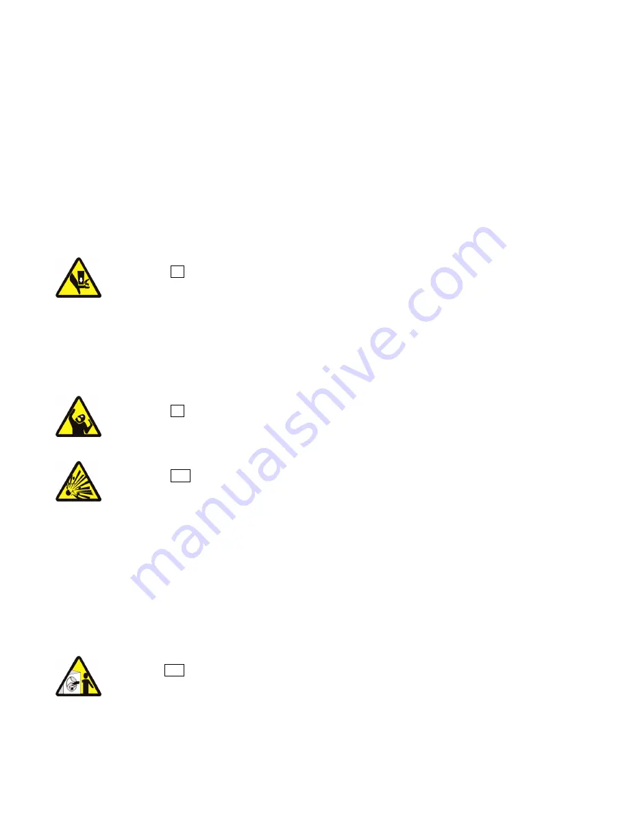
WARNING  8 : Crush Hazards

—Contact with the turning cylinder can crush your limbs. The

cylinder will repel any object you try to stop it with, possibly causing the object to strike or stab

you. The turning cylinder is normally isolated by the locked cylinder door.
• Do not attempt to open the door or reach into the cylinder until the cylinder is stopped.
• Do not place any object in the turning cylinder.
• Do not operate the machine with a malfunctioning door interlock.
• Open pocket machines only—Keep yourself and others clear of cylinder and goods during

jogging operation.

• Do not operate the machine with malfunctioning two-hand manual controls.

WARNING  9 : Confined Space Hazards

—Confinement in the cylinder can kill or injure

you. Hazards include but are not limited to panic, burns, poisoning, suffocation, heat prostration,

biological contamination, electrocution, and crushing.
• Do not attempt unauthorized servicing, repairs, or modification.

WARNING  10 : Explosion and Fire Hazards

—Flammable substances can explode or

ignite in the cylinder, drain trough, or sewer. The machine is designed for washing with water,

not any other solvent. Processing can cause solvent-containing goods to give off flammable

vapors.
• Do not use flammable solvents in processing.
• Do not process goods containing flammable substances. Consult with your local fire

department/public safety office and all insurance providers.

5.

Safety Alert Messages—Unsafe Conditions

 [Document BIUUUS14]

5.1.

Damage and Malfunction Hazards

5.1.1.

Hazards Resulting from Inoperative Safety Devices

DANGER  11 : Entangle and Sever Hazards

—Cylinder door interlock—Operating the

machine with a malfunctioning door interlock can permit opening the door when the cylinder is

turning and/or starting the cycle with the door open, exposing the turning cylinder.
• Do not operate the machine with any evidence of damage or malfunction.

9

Содержание 42044SR2

Страница 1: ...er ECN MAIHYDWECE 2018214A Publishing System TPAS2 Access date 05 23 2018 Document ECNs Latest Installation 42044 60044 72044 SR2 SR3 WR2 WR3 PELLERIN MILNOR CORPORATION POST OFFICE BOX 400 KENNER LOUISIANA 70063 0400 U S A ...

Страница 2: ......

Страница 3: ...rvice connections MSIN0201BE 2002372V 46 Reuse Tank Installation and Operation MSINA409AE 199841AV 49 2 Dimensional Drawings 51 Dimensional Drawing 42044SR2 42044SR3 BD4244SPCE 2017355D 52 Dimensional Drawing 42044SR2 42044SR3 Options BD4244SPCB 2017355D 53 Dimensional Drawing 42044WR2 42044WR3 BD4244WPCE 2017355D 54 Dimensional Drawing 42044WR2 42044WR3 Options BD4244WPCB 2017355D 55 Dimensional ...

Страница 4: ......

Страница 5: ...is warranty For parts which require routine replacement due to normal wear such as gaskets contact points brake and clutch linings belts hoses and similar parts the warranty time period is 90 days We reserve the right to make changes in the design and or construction of our equipment including purchasedcomponents withoutobligationtochangeanyequipmentpreviouslysupplied ANY SALE OR FURNISHING OF ANY...

Страница 6: ...ou can also get components from the Milnor factory Tell the supplier the machine model and serial number and this data for each necessary component The component number from this manual The component name if known The necessary quantity The necessary transportation requirements If the component is an electrical component give the schematic number if known If the component is a motor or an electric...

Страница 7: ...emarks AutoSpot GreenTurn Milnor PulseFlow CBW GreenFlex MilMetrix PurePulse Drynet Hydro cushion MilTouch Ram Command E P Express Linear Costa Master MilTouch EX RecircONE E P OneTouch Linear Costo Miltrac RinSave E P Plus Mentor MultiTrac SmoothCoil Gear Guardian Mildata PBW Staph Guard End of document BNUUUU02 BNUUUU02 2017285A BNUUUU02 0000158094 A 3 7 13 17 1 53 PM Released 3 ...

Страница 8: ......

Страница 9: ...Installation 1 5 ...

Страница 10: ...cted to those employees given the task of using it only specifically designated workers carry out repairs modifications maintenance or servicing information instruction and training is provided workers and or their representatives are consulted Work equipment must comply with the requirements listed below The owner user must verify that installation and maintenance of equipment is performed in suc...

Страница 11: ...ided on the machine safety placards in the Safety Guide and throughout the other machine manuals Placards must be kept clean so that the information is not obscured They must be replaced immediately if lost or damaged The Safety Guide and other machine manuals must be available at all times to the appropriate personnel See the machine service manual for safety placard part numbers Contact the Miln...

Страница 12: ...ed door The moving door can strike you or crush or pinch your limbs if caught between the door and machine Some doors move automatically Keep yourself and others clear of movement areas and paths Keep both hands on the controls while operating Do not operate the machine with malfunctioning two hand manual controls WARNING 5 Crush Hazards Tilting machines only The machine can crush your body or lim...

Страница 13: ...e with a malfunctioning door interlock Open pocket machines only Keep yourself and others clear of cylinder and goods during jogging operation Do not operate the machine with malfunctioning two hand manual controls WARNING 9 Confined Space Hazards Confinement in the cylinder can kill or injure you Hazards include but are not limited to panic burns poisoning suffocation heat prostration biological ...

Страница 14: ...ll or injure personnel further damage or destroy the machine damage property and or void the warranty Do not operate a damaged or malfunctioning machine Request authorized service WARNING 17 Explosion Hazards Cylinder A damaged cylinder can rip apart during extraction puncturing the shell and discharging metal fragments at high speed Do not operate the machine with any evidence of damage or malfun...

Страница 15: ...t tagout standard when lockout tagout is called for in the service instructions Outside the USA abide by the OSHA standard in the absence of any other overriding standard WARNING 22 Crush Hazards Tilting machines only The machine housing will crush your body or limbs if it descends or falls while you are under it Housing can descend with power off or on Manual operation of tilting valves overrides...

Страница 16: ...ty to safely withstand our published forces without transmitting undue vibration If the subsoil has subsided or if the floor slab itself has insufficient strength and rigidity a deeper foundation poured as to become monolithic with the floor slab may be required Support pilings may even be required if the subsoil itself is springy i e if its resonant frequency is near the operating speed of the ma...

Страница 17: ...r structural engineer must be engaged for this purpose Figure 1 How Rotating Forces Act on the Foundation Typical Machine Legend A Direction of force B Load C Rotation Frequency RPM 60 Figure 1 above is intended to depict both on grade and above grade installations and is equally applicable to flexibly mounted washer extractors as well as to rigid models installed either directly on a floor slab o...

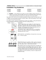
Страница 18: ...s symbol appears on most tags The machine ships with safety operator and routine maintenance guides for customer use Milnor dealer manuals for installing commissioning and servicing the machine are also available from the Milnor Parts department B2TAG88005 This carefully built product was tested and in spected to meet Milnor performance and quality standards by identification mark of tester B2TAG9...

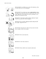
Страница 19: ...power connections as ex plained in the schematic manual B2TAG94117 The brake assembly under the machine is fragile Fork lift only under main structural supports B2TAG94118 Do not strike shipping container during fork lift ing Fragile components inside B2TAG96007 Add grease here Refer to the preventive mainte nance schedule in the service manual B2T2001013 Hot water connection B2T2001014 Cold water...

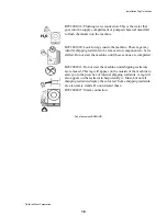
Страница 20: ...d Do not start the machine until these actions are completed B2T2002013 Do not start the machine until shipping restraints are removed This tag will appear on the outside of the machine to alert you to the presence of internal shipping restraints A tag will also appear on the restraint to help identify it Most but not all shipping restraints display the color red Some shipping restraints are also ...

Страница 21: ...rous Chemical Supplies and Wash Formulas Some examples that can cause damage are a very high concentration of chlorine bleach a mixture of acid sour and hypo chlorite chemical supplies examples chlorine bleach hydrofluosilicic acid that stay on the stainless steel because they are not quickly flushed with water The book Textile Laundering Technology by Charles L Riggs gives data about correct chem...

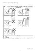
Страница 22: ...Let the Chemical Supply Go In the Machine by a Siphon Schematic Views Legend P Pump T Chemical tank S The siphon occurs above here Liquid in the gray parts of the chemical tube and tank can go in the machine Prevent Damage from Chemical Supplies and Chemical Systems 18 ...

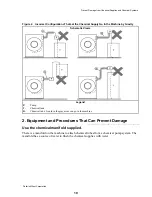
Страница 23: ...ay areas can go in the machine 2 Equipment and Procedures That Can Prevent Damage BNUUUR02 R02 0000160545 A 2 A 8 8 30 17 3 28 PM Released Use the chemical manifold supplied There is a manifold on the machine to attach chemical tubes from a chemical pump system The manifold has a source of water to flush the chemical supplies with water Prevent Damage from Chemical Supplies and Chemical Systems 19...

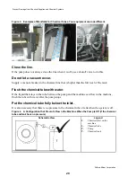
Страница 24: ...er If the liquid that stays in the tube between the pump and the machine can flow in the machine flush the tube with water after the pump stops Put the chemical tube fully below the inlet It is also necessary that there is no pressure in the chemical tube or tank when the system is off Figure 4 A Configuration that Prevents Flow in the Machine When the Pump is Off if the chemical tube and tank hav...

Страница 25: ...u do maintenance on the chemical pump system Use the correct components Make sure that all connections are the correct fit Make sure that all connections are tight End of document BNUUUR02 Prevent Damage from Chemical Supplies and Chemical Systems 21 ...

Страница 26: ...y switch Remove these items just prior to opera tion Ê Site Requirements Ë Space Requirements 1 All openings and corridors through which equipment must pass during installation must be large enough to ac comodate the width and the height of the machine as shown on the dimensional drawings It is occasional ly possible to reduce the overall dimensions by removing piping or other special modification...

Страница 27: ...fety switch Remove these items just prior to opera tion Ê Site Requirements Ë Space Requirements 1 All openings and corridors through which equipment must pass during installation must be large enough to ac comodate the width and the height of the machine as shown on the dimensional drawings It is occasional ly possible to reduce the overall dimensions by removing piping or other special modificat...

Страница 28: ...er Switch to FORMULA or to ON as appropriate to activate the push downs then remove hold down bolts and plates marked with red which hold the shell to the frame De energize machine 6 On 42 and 48 tilting machines only remove the four hold down bolts marked with red that hold the lower side frame channels to the base pad On 64 tilt forward only machines BTL models remove the rear tilt wheel clamps ...

Страница 29: ...er Switch to FORMULA or to ON as appropriate to activate the push downs then remove hold down bolts and plates marked with red which hold the shell to the frame De energize machine 6 On 42 and 48 tilting machines only remove the four hold down bolts marked with red that hold the lower side frame channels to the base pad On 64 tilt forward only machines BTL models remove the rear tilt wheel clamps ...

Страница 30: ... grout under the full length of each base pad Take care to fill all voids with grout to assure that there is a solid base of grout under each base pad for additional information see Grouting and Anchoring Considera tions in this section 4 When the grout has hardened remove the shell hold down bolts The shell will be lifted by the HYDRO CUSHION springs so that the temporary blocking may be removed ...

Страница 31: ... grout under the full length of each base pad Take care to fill all voids with grout to assure that there is a solid base of grout under each base pad for additional information see Grouting and Anchoring Considera tions in this section 4 When the grout has hardened remove the shell hold down bolts The shell will be lifted by the HYDRO CUSHION springs so that the temporary blocking may be removed ...

Страница 32: ...e pads and existing floor Voids must not exist Ë G routing and Anchoring Considerations Observe the following considerations when applying grout and anchoring machine Use only industrial strength non shrinking grout Pack or trowel by hand If the grout after mixing is too thin causing it to flow from under the base pads install temporary cardboard framing around pads to retain the grout until it cu...

Страница 33: ...t it cannot swing open during installation 5 The hold down bolts brackets and spacers marked with red that hold the shell rigid in the frame must be removed prior to operation However they should not be loosened until the machine is ready to be grouted In addition the tie wrap that secures the vibration safety switch see FIGURE 8 must be removed after installa tion and before operation Ê Site Requ...

Страница 34: ...hat it cannot swing open during installation 5 The hold down bolts brackets and spacers marked with red that hold the shell rigid in the frame must be removed prior to operation However they should not be loosened until the machine is ready to be grouted In addition the tie wrap that secures the vibration safety switch see FIGURE 8 must be removed after installa tion and before operation Ê Site Re...

Страница 35: ...r to the machine dimensional drawing Once the foundation is prepared the shipping skids are removed and the machine is ready to be set in its desired position See FIGURES 3 and 7 then proceed as follows 1 Lower the machine onto three short lengths of 2 x 4 s such that the shell front is resting on two of them and the third is centered under the shell back 2 Put shims on top of the 2 x 4 s until th...

Страница 36: ...ed if desired Once the foundation is prepared the shipping skids are removed and the machine is ready to be set in its desired position See FIGURES 3 and 7 then proceed as follows 1 Lower the machine onto three short lengths of 2 x 4 s such that the shell front is resting on two of them and the third is centered under the shell back 2 Put shims on top of the 2 x 4 s until the machine has approxima...

Страница 37: ...Î FIGURE 8 MSIN0301AE Î Vibration Switch Î FIGURE 9 MSIN0301AE Î 60 Staph Guard 33 ...

Страница 38: ... per plumbing code see Piped Inlet Precautions in this section Hot water inlet Third water inlet Reuse water inlet Steam inlet See dimensional drawing for size 30 115 PSI 2 10 4 57 kilogram centimeter Pipe material per plumbing code see Steam Precautions in this section Flushing water for supply injector Divided cylinder 52 and 72 open pocket non tilt machines only See dimensional drawing for size...

Страница 39: ...ial per plumbing code see Piped Inlet Precautions in this section Hot water inlet Third water inlet Reuse water inlet Steam inlet See dimensional drawing for size 30 115 PSI 2 10 4 57 kilogram centimeter Pipe material per plumbing code see Steam Precautions in this section Flushing water for supply injector Divided cylinder 52 and 72 open pocket non tilt machines only See dimensional drawing for s...

Страница 40: ...a 2 1 E Î FIGURE 5 MSIN0210BE Î 72044 Non Tilting Open Pocket Service Connections 72044WTx 52038WTx 1 Hot 2 Cold 3 Third or Reuse water 4a Steam 72044WTx 4b Steam 52038WTx 5 Compressed air E Electric connection 4b E 4a 3 2 1 5 Î FIGURE 6 MSIN0201BE Î 72044 and 52038 Tilting Open Pocket Service Connections Valves on rear 48032BTx 48036QTx 1 Hot 2 Cold 3 Third or Reuse water 4 Steam 5 Compressed air...

Страница 41: ...a 2 1 E Î FIGURE 5 MSIN0210BE Î 72044 Non Tilting Open Pocket Service Connections 72044WTx 52038WTx 1 Hot 2 Cold 3 Third or Reuse water 4a Steam 72044WTx 4b Steam 52038WTx 5 Compressed air E Electric connection 4b E 4a 3 2 1 5 Î FIGURE 6 MSIN0201BE Î 72044 and 52038 Tilting Open Pocket Service Connections Valves on rear 48032BTx 48036QTx 1 Hot 2 Cold 3 Third or Reuse water 4 Steam 5 Compressed air...

Страница 42: ...ion Divided cylinder machines require a separate cold water connection Ë Optional Spray down Water Connection Rapid load machines use a separate cold water connec tion A machine equipped for both cooldown and spray down uses one inlet for both functions Ë Liquid Supplies Machines equipped with the optional central liquid supply injection in lieu of a flushing supply have a set of supply valves and...

Страница 43: ...ion Divided cylinder machines require a separate cold water connection Ë Optional Spray down Water Connection Rapid load machines use a separate cold water connec tion A machine equipped for both cooldown and spray down uses one inlet for both functions Ë Liquid Supplies Machines equipped with the optional central liquid supply injection in lieu of a flushing supply have a set of supply valves and...

Страница 44: ...plate fuse sizes must not be applied to standard fuses 6 See nameplate and wire sizing information in the schematic manual for fuse and wire sizes For wire runs of more than 50 feet 15 24 increase by one wire size per each additional 50 feet 15 24 7 Verify all motor rotation see the Mark II washer extractor reference manual for further information Ê Electric Power Connections Voltage fluctuations ...

Страница 45: ...plate fuse sizes must not be applied to standard fuses 6 See nameplate and wire sizing information in the schematic manual for fuse and wire sizes For wire runs of more than 50 feet 15 24 increase by one wire size per each additional 50 feet 15 24 7 Verify all motor rotation see the Mark II washer extractor reference manual for further information Ê Electric Power Connections Voltage fluctuations ...

Страница 46: ... the machine will extract quite satisfactorily whenever the air pressure is above 85 PSI but will not enter extraction at all when the pressure is below 85 PSI Î FIGURE 16 MSIN0201BE Î All Machines THIS HOSE FROM THE STAPH AIRTROL ASSEMBLY TO THE CLEAN SIDE VENT SCREEN WAS REMOVED FOR SHIPPING PURPOSES TO PERMIT ATTACHMENT OF LOADING SLING TO SHIPPING EYE BOLT REINSTALL AS SHOWN BEFORE OPERATING M...

Страница 47: ... the machine will extract quite satisfactorily whenever the air pressure is above 85 PSI but will not enter extraction at all when the pressure is below 85 PSI Î FIGURE 16 MSIN0201BE Î All Machines THIS HOSE FROM THE STAPH AIRTROL ASSEMBLY TO THE CLEAN SIDE VENT SCREEN WAS REMOVED FOR SHIPPING PURPOSES TO PERMIT ATTACHMENT OF LOADING SLING TO SHIPPING EYE BOLT REINSTALL AS SHOWN BEFORE OPERATING M...

Страница 48: ...less than about 10 seconds because the opening and closing time of the chemical inlet valve would become a large percentage of the injection time and thus cause certain variations in the amount of chemical actually injected FIGURE 1 O 90 O 7 6 O 6 2 O 4 7 FLOW VALVE POSITIONING REF 25 47 50 62 75 76 FULL 90 O O O O TABLE 1 Î FIGURE 19 MSIN0201BE ÎCentral Liquid Supply Systems WATER CONNECTION FOR ...

Страница 49: ...less than about 10 seconds because the opening and closing time of the chemical inlet valve would become a large percentage of the injection time and thus cause certain variations in the amount of chemical actually injected FIGURE 1 O 90 O 7 6 O 6 2 O 4 7 FLOW VALVE POSITIONING REF 25 47 50 62 75 76 FULL 90 O O O O TABLE 1 Î FIGURE 19 MSIN0201BE ÎCentral Liquid Supply Systems WATER CONNECTION FOR ...

Страница 50: ...FTXVWcb 42044WP2 60044WP2 Assembled reuse tank 390 Pounds 177 Kilograms 550 Pounds 250 Kilograms Reuse pump 150 Pounds 68 Kilograms 300 Pounds 136 Kilograms UbQdY_ The reuse system is automatically controlled by the washer extractor wash program as follows When the wash program calls for reuse drain the washer extractor opens the reuse drain and signals the reuse pump to start The reuse drain clos...

Страница 51: ...586DA4 BUecU CicdU CSXU QdYS B5EC5 D1 9 CD1 1D9 1 4 5B1D9 C9 1 15 1F _V 47 ...

Страница 52: ...DQ _e d G cX_g 586DA4 BUQb BUecU DQ _e d G cX_g 586DA4 UVd 6b_ d BUecU DQ _e d G cX_g 586DA4 BUecU DQ 9 _cYdY_ G cX_g 586DA4 BUecU Y Y W 4UdQY c G cX_g 586DA4 BUecU e 4UdQY c G cX_g B5EC5 D1 9 CD1 1D9 1 4 5B1D9 C9 1 15 1F _V 48 ...

Страница 53: ...Dimensional Drawings 2 49 ...

Страница 54: ......

Страница 55: ...51 ...

Страница 56: ...52 ...

Страница 57: ...53 ...

Страница 58: ...54 ...

Страница 59: ...55 ...

Страница 60: ...56 ...

Страница 61: ...57 ...

Страница 62: ...58 ...

Страница 63: ...59 ...

Страница 64: ......

Страница 65: ...61 ...

Страница 66: ...62 ...

Страница 67: ...63 ...

Страница 68: ...64 ...

Отзывы: