MSIN0301AE/9439AV (1 of 3)
È
HANDLING AND SETTING PROCEDURES FOR
DIVIDED CYLINDER, HYDRO-CUSHION
®
MACHINES
Ê
Handling Precautions
1. Remove the protective coverings (leaving the
machine on shipping skids) and examine carefully
for possible shipping damage. If the machine is
damaged, notify the transportation company
immediately.
NOTE: Once the machine is given to the carrier for
delivery, it is solely the responsibility of the car-
rier to ensure that no damage occurs during transit.
In addition to readily apparent damage, carriers are
liable for concealed damage. Do not hesitate to
file a claim with a carrier if the machine is
damaged in any way during shipment. Milnor
®
will be glad to assist you in filing your claim, but
is not responsible for any shipping damage to the
machine once it has been delivered to the carrier in
good condition.
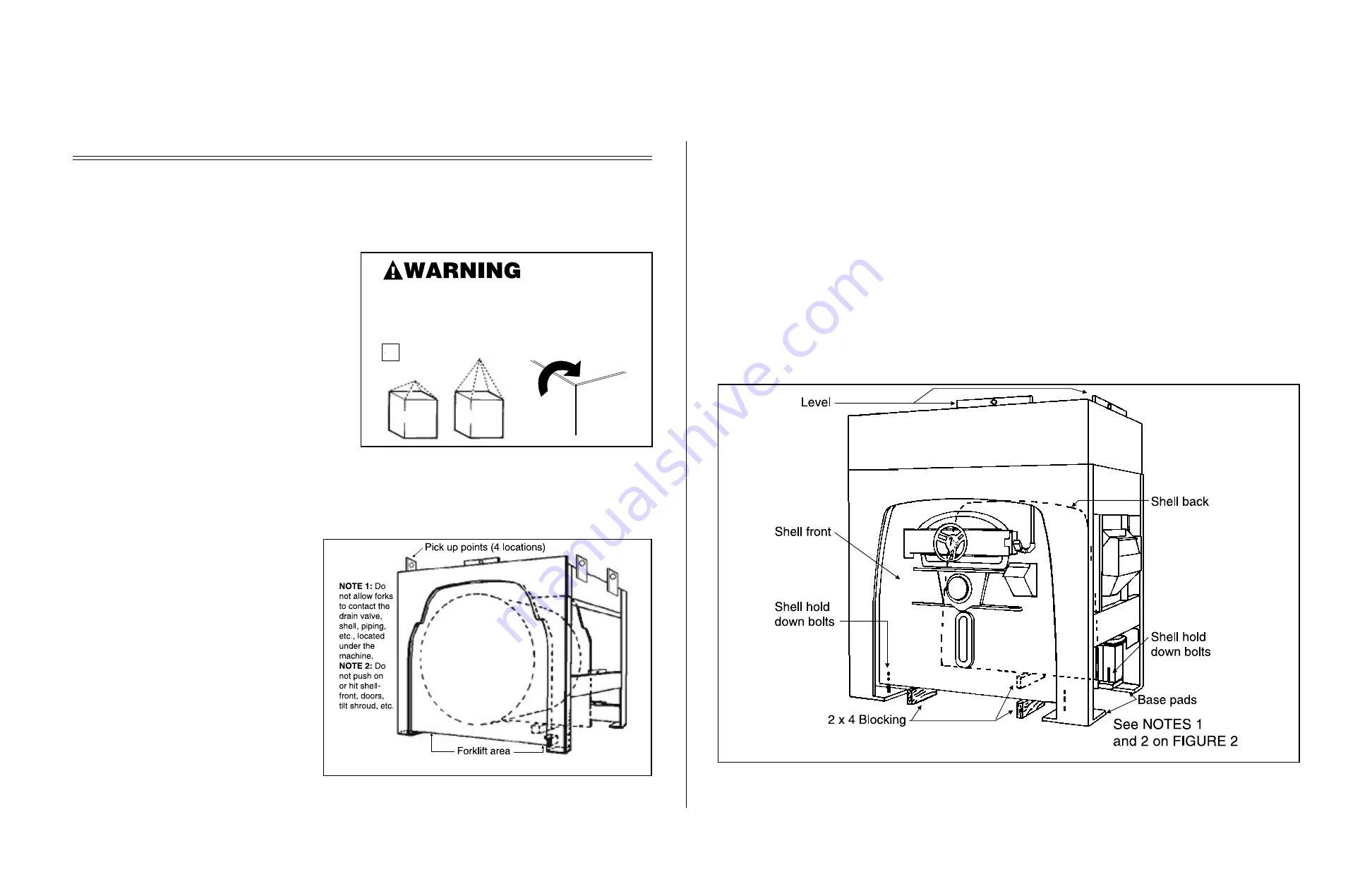
2. When lifting an uncrated machine by crane, always connect to the four lifting rings provided. Use skids for
fork lifting. Once the skids are removed, take care in placing forks under the machine. Do not allow the
forks to come in contact with the drain
valve, shell, piping, etc., located under
the machine.
3. Never push, pull, or exert pressure on any
components which protrude from the
machine frame, such as the shell front,
door, supply injector, electric boxes, con-
trols, belt guards, inlet piping, etc.
4. Be sure shell door(s) is secured so that it
cannot swing open during installation.
5. The hold down bolts, brackets, and spacers
(marked with red) that hold the shell rigid
in the frame must be removed prior to
operation. However, they should not be
loosened until the machine is ready to be
grouted. In addition, the tie wrap that
secures the vibration safety switch (see
FIGURE 8) must be removed after installa-
tion and before operation.
Ê
Site Requirements
Ë
Space Requirements
1. All openings and corridors through which equipment must pass during installation must be large enough to ac-
comodate the width and height of the machine (as shown on the dimensional drawings). It is occasionally
possible to reduce the overall dimensions by removing piping or other special modifications. Consult Mil-
nor
®
for additional information.
2. Sufficient clearance must be provided for normal operation and maintenance procedures.
Ë
Operational Requirements
1. Allow sufficient ventilation for the heat and vapors of normal operation to dissipate.
2. Provide easy access to controls. Operators must be able to view all status lights and reach all controls as-
sociated with the machine (e.g., electrical power connections, water and steam shut-offs).
Rigger is liable for
damages both directly
and indirectly caused
by rigging.
4 point pick-up
wrong
right
NOTE
ON SOME MODELS,
LIFTING POINTS ARE
CONCEALED BEHIND
BELT GUARD.
Î
FIGURE 1
(MSIN0301AE)
Î
LIfting Instructions
Î
FIGURE 2
(MSIN0301AE)
Î
Pickup and Forklift Area
Î
FIGURE 3
(MSIN0301AE)
Î
Setting a Divided Cylinder Machine
(Procedure applies to all Divided cylinders and Staph-Guards
®
)
30
Содержание 42044SR2
Страница 2: ......
Страница 4: ......
Страница 8: ......
Страница 9: ...Installation 1 5 ...
Страница 37: ...Î FIGURE 8 MSIN0301AE Î Vibration Switch Î FIGURE 9 MSIN0301AE Î 60 Staph Guard 33 ...
Страница 51: ...586DA4 BUecU CicdU CSXU QdYS B5EC5 D1 9 CD1 1D9 1 4 5B1D9 C9 1 15 1F _V 47 ...
Страница 53: ...Dimensional Drawings 2 49 ...
Страница 54: ......
Страница 55: ...51 ...
Страница 56: ...52 ...
Страница 57: ...53 ...
Страница 58: ...54 ...
Страница 59: ...55 ...
Страница 60: ...56 ...
Страница 61: ...57 ...
Страница 62: ...58 ...
Страница 63: ...59 ...
Страница 64: ......
Страница 65: ...61 ...
Страница 66: ...62 ...
Страница 67: ...63 ...
Страница 68: ...64 ...

